
Vane pump

a technology of vane and lubricating oil, which is applied in the direction of rotary/oscillating piston pump components, machines/engines, liquid fuel engines, etc., can solve problems such as vane damage, and achieve the effect of reducing the leakage of lubricating oil and easy sucking

Active Publication Date: 2012-06-21
TAIHO INDUSTRIES CO LTD
View PDF6 Cites 8 Cited by
  • Summary
  • Abstract
  • Description
  • Claims
  • Application Information

AI Technical Summary

Benefits of technology

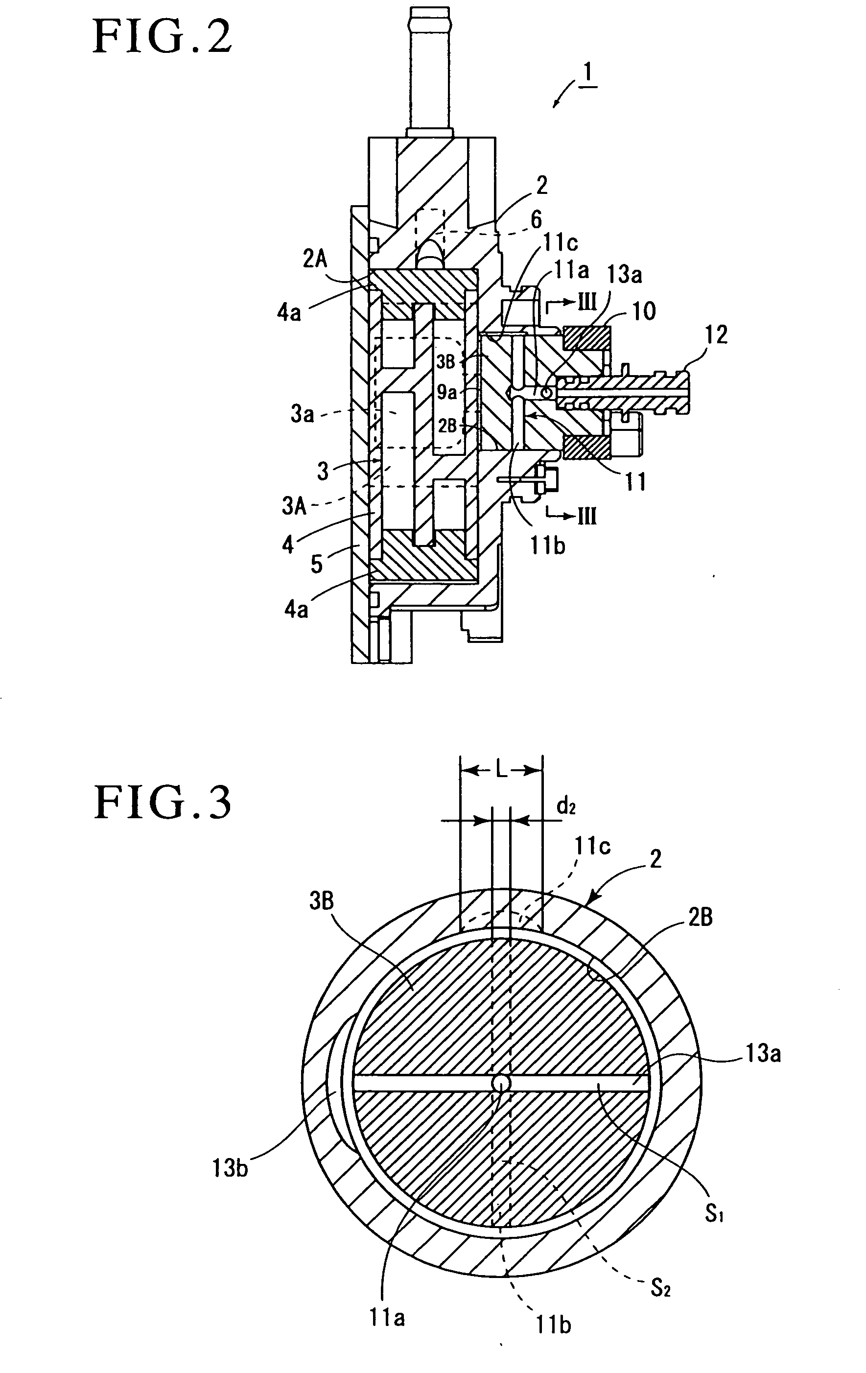
[0013]Generally, the passage area S1 of the gas passage is set to be as small a passage area S1 as possible in order to reduce the leakage of the lubricating oil to the outer space through the gas passage, i.e., to an internal space of an engine, when the hydraulic pressure of the lubricating oil supplied from the hydraulic pump to the oil supply passage is high.
[0014]On the other hand, conventionally, particular attention has not been paid to size relations of the above-described passage area S2 of the oil supply passage, passage area S3 of the oil supply pipe, diameter d2 of the diameter direction oil supply hole, and width L of the oil supply groove in the rotational direction of the rotor from a viewpoint that it is only necessary to supply a required lubricating oil to the pump chamber.
[0015]However, in the present invention, in order to prevent the air of the outer space from being sucked into the pump chamber from the gas passage as much as possible when the hydraulic pressure of the lubricating oil supplied from the hydraulic pump to the oil supply passage is low, the passage area S2 of the oil supply passage is set to be in the range of S1<S2≦3×S1. Namely, the passage area S2 of the oil supply passage is set to be a relatively small passage area that is at most three times larger than the passage area S1 that is as small as possible of the gas passage to thereby make the air difficult to be sucked. It is to be noted that the passage area S2 of the oil supply passage disclosed in FIG. 3 of the above-described Patent Document 1 is set to be approximately sixteen times as large as the passage area S1 of the gas passage, which is a comparison based on a drawing.
[0016]On the other hand, the passage area S2 of the oil supply passage is set to be larger than the passage area S1 of the gas passage, so that the required lubricating oil is reliably supplied in the pump chamber during operation beyond idling of the vane pump.
[0017]Next, in the present invention, the passage area S3 of the oil supply pipe is set to be in the range of S2<S3≦3×S2 with respect to the passage area S2 of the oil supply passage set to be relatively small. This is because a squeezing effect can be obtained by making the passage area S3 of the oil supply pipe larger than the passage area S2 of the oil supply passage, and thereby a hydraulic pressure in the oil supply passage can be kept as high as possible even with a small amount of lubricating oil at the time of idling.
[0018]Further, in the present invention, the width L of the axial direction oil supply groove is set to be in the range of d2<L<4×d2. The opening of the diameter direction oil supply hole intermittently crosses the axial direction oil supply groove by the rotation of the rotor, and when crossing it, the opening is overlapped to be in communication with the groove. However, when the width L of the axial direction oil supply groove is set to be too large, a time of communication, i.e., an overlap time, becomes longer, and particularly when the hydraulic pressure of the oil supply passage at the time of idling is low, the air is easily sucked due to vacuum of the pump chamber.

Problems solved by technology

If a large amount of lubricating oil is then drawn into the pump chamber, an excessive load is added to the vanes when the vane pump is subsequently started in order to discharge the lubricating oil, which may cause a damage on the vane.

Method used


Image

  • Vane pump
  • Vane pump
  • Vane pump

Examples


Embodiment Construction

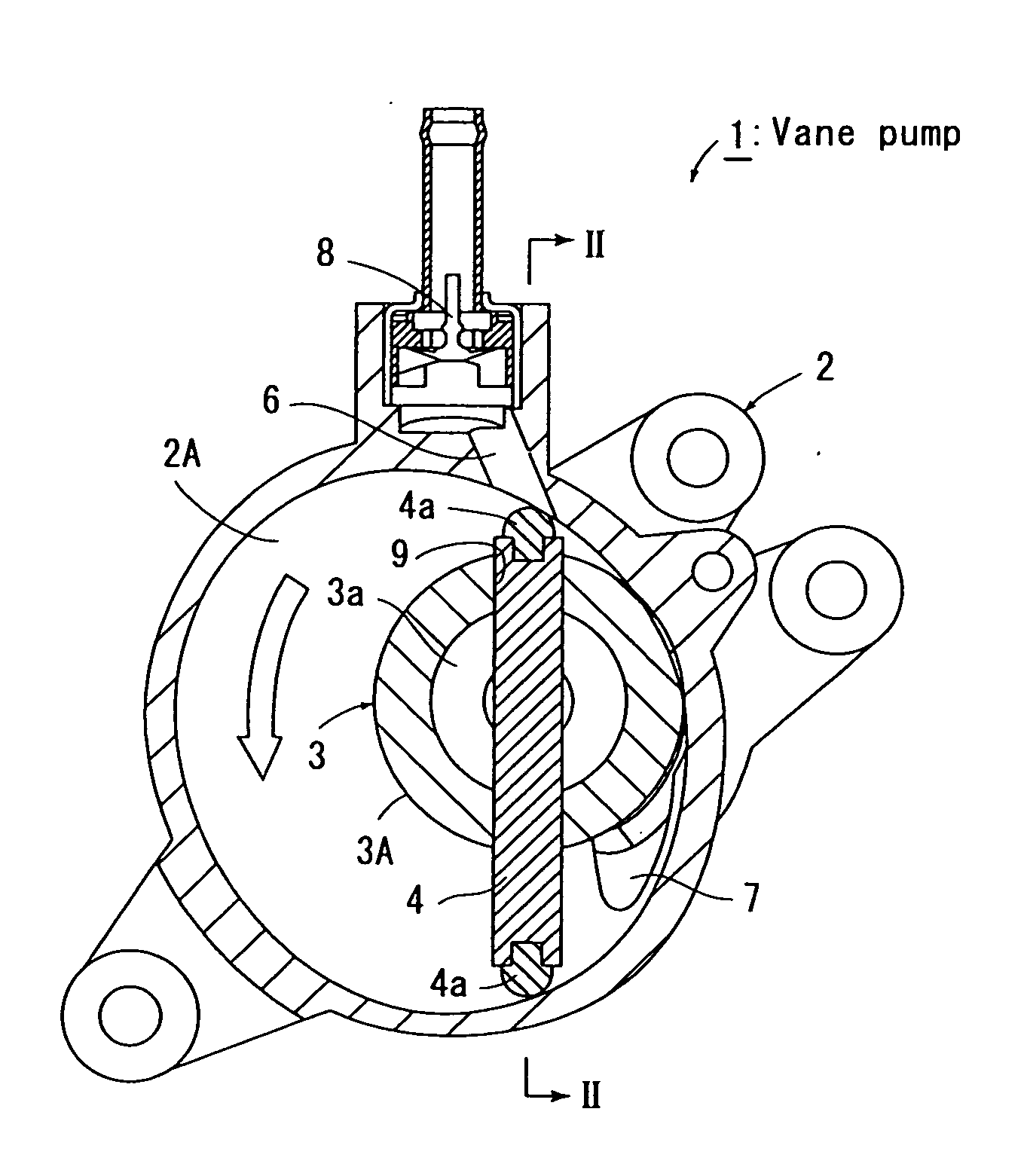
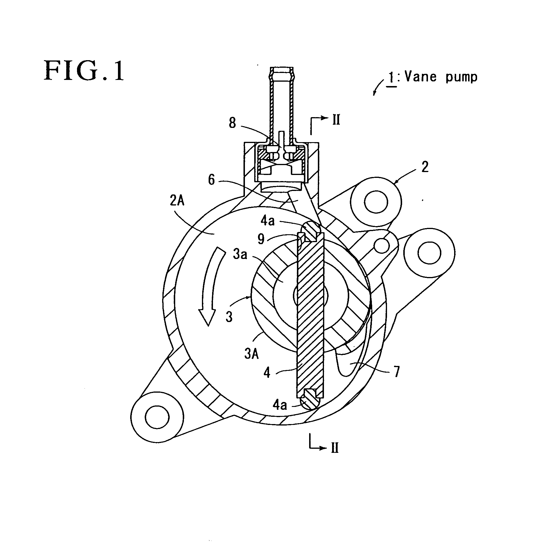
[0025]Hereinafter, when describing an embodiment shown in drawings of the present invention, FIGS. 1 and 2 show a vane pump 1 according to the present invention, and this vane pump 1 is fixed to a side surface of an engine of an automobile, which is not shown, to generate a negative pressure in a servo unit for a brake system, which is not shown.

[0026]This vane pump 1 includes: a housing 2 in which a substantially circular pump chamber 2A is formed; a rotor 3 that is rotated by an engine drive force about a position eccentric with respect to a center of the pump chamber 2A; a vane 4 that is rotated by the rotor 3 and that always partitions the pump chamber 2A into a plurality of spaces; and a cover 5 that closes the pump chamber 2A.

[0027]The housing 2 is provided with an intake air passage 6 that communicates with the servo unit for the brake to suck a gas from the servo unit, the intake air passage 6 being located at an upper part of the pump chamber 2A, and a discharge passage 7 f...


PUM


Abstract

A lubricating oil from an oil supply pipe 12 is supplied to a pump chamber 2A through an axial direction oil supply hole 11a of an oil supply passage 11, a diameter direction oil supply hole 11b, and an axial direction oil supply groove 11c. A gas passage 13 includes a diameter direction gas hole 13a and an axial direction gas groove 13b, and the diameter direction gas hole 13a is made to communicate with the axial direction gas groove 13b when the diameter direction oil supply hole 11b is made to communicate with the axial direction oil supply groove 11c. When a passage area of the gas passage is defined as S1, a passage area of the oil supply passage is S2, a passage area of the oil supply pipe is S3, a diameter of the diameter direction oil supply hole is d2, and a width of the axial direction oil supply groove in a rotational direction of a rotor is L, the passage area S2 of the oil supply passage is set to be in a range of S1<S2≦3×S1, and the passage area S3 of the oil supply pipe is S2<S3≦3×S2, and further the width L of the oil supply groove is d2<L<4×d2.It can be prevented as much as possible that the air is sucked into the pump chamber from the gas passage 13 to thereby increase engine driving torque.

Description

TECHNICAL FIELD[0001]The present invention relates to a vane pump and, more particularly, to a vane pump in which an oil supply passage through which a lubricating oil flows is formed inside a rotor, and in which the lubricating oil is intermittently supplied in a pump chamber by a rotation of the rotor.BACKGROUND ART[0002]Conventionally, a vane pump has been known, which includes: a housing including a substantially circular pump chamber; a rotor that rotates about a position eccentric with respect to a center of the pump chamber; a vane that is rotated by the rotor and that always partitions the pump chamber into a plurality of spaces; an oil supply passage that intermittently communicates with the pump chamber by the rotation of the rotor; an oil supply pipe that is connected to this oil supply passage to supply a lubricating oil from a hydraulic pump thereto; and a gas passage that makes the pump chamber and an outer space communicate with each other when the oil supply passage ...

Claims


Application Information

Patent Timeline
Patent Type & Authority Applications(United States)
IPC IPC(8): F04C29/02F04C18/344
CPCF04C18/3441F04C29/12F04C29/028F04C25/02F04C18/344F04C29/02
Inventor SAKAKIBARA, RYUICHIHAYASHIDA, KIKUJIOHTAHARA, KIYOTAKAKUNO, YOSHIMASA
Owner TAIHO INDUSTRIES CO LTD
Learn More