
Fiberglass mesh scrim reinforced cementitious board system

a technology of cementitious boards and fiberglass mesh, which is applied in the direction of knotting, solid waste management, braiding, etc., can solve the problems of fiberglass, lack of chemical attack resistance of cement ingredients, and substantial unaffected by water, so as to improve the long-term durability of the resulting mesh, improve the runnability and field performance, and the effect of increasing the density

Inactive Publication Date: 2012-06-14
UNITED STATES GYPSUM CO
View PDF2 Cites 53 Cited by
  • Summary
  • Abstract
  • Description
  • Claims
  • Application Information

AI Technical Summary

Benefits of technology

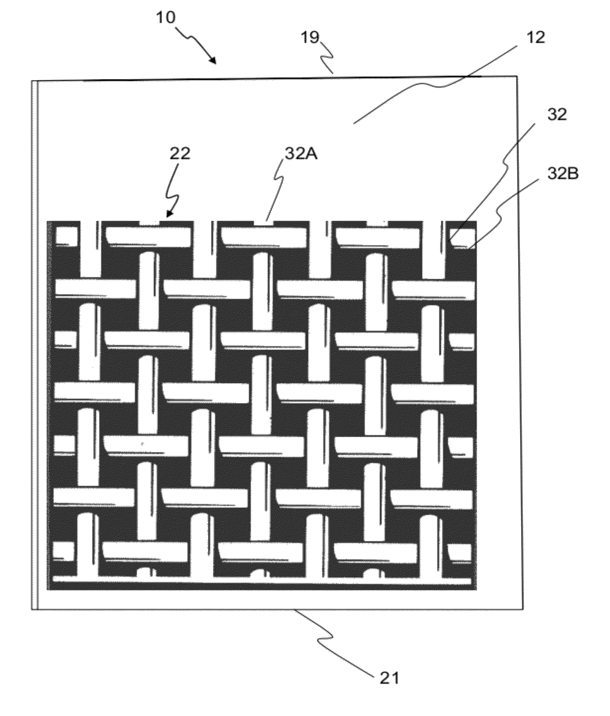
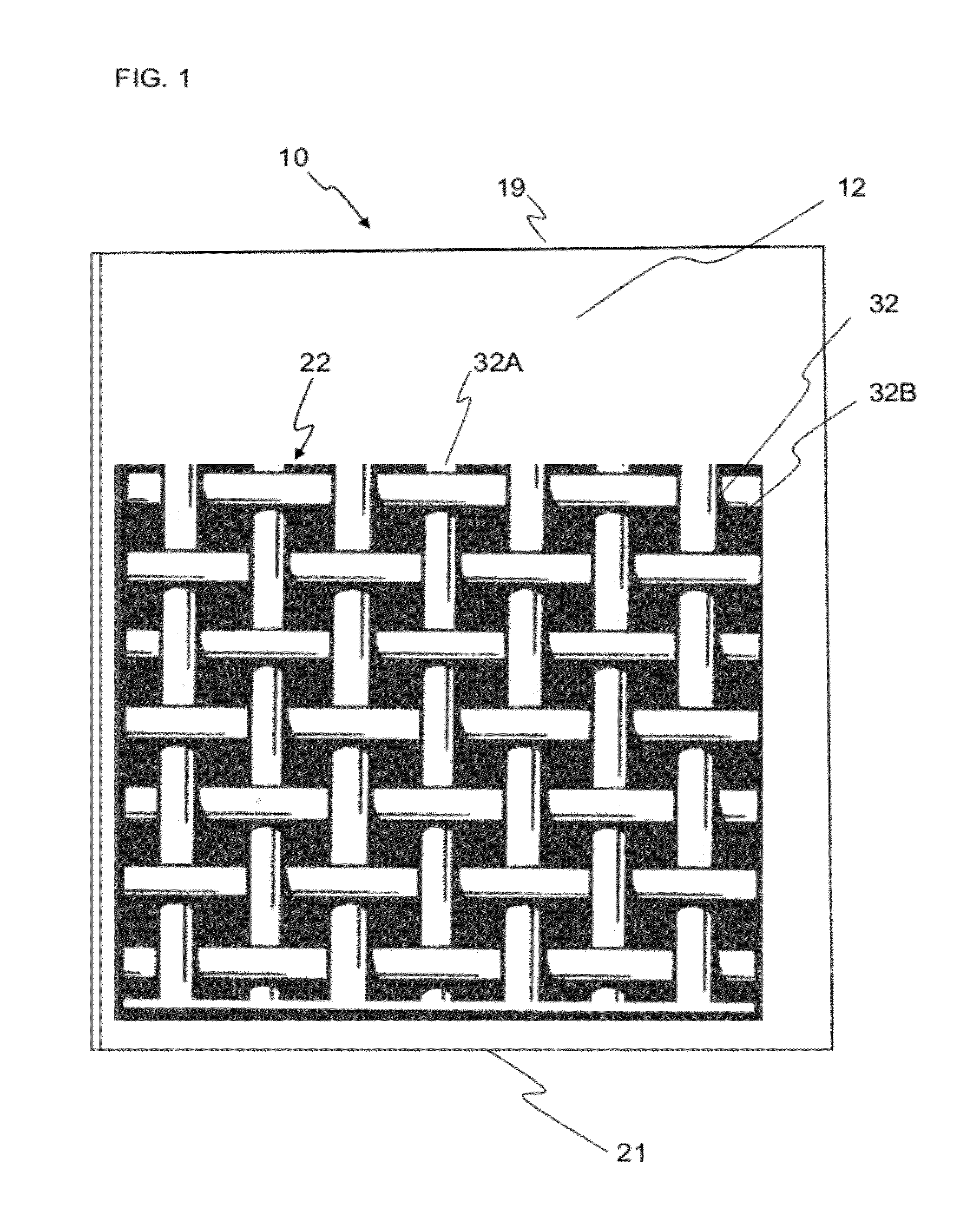
[0021]The present invention relates to a new and improved cementitious panel, such as cement board, reinforced to have improved Runnability and field performance. The improved mesh made from fiberglass such as E-glass, and coated with water resistant and alkali resistant coating. The fiberglass yarn is thicker and has higher density than conventional fiberglass yarn fabric and has larger mesh grid openings between the fiber. This allows easier passage of cementitious slurry through the grid openings for more uniform coverage of the slurry layer over the embedded mesh and yet provides improved long term durability of the resulting mesh scrim reinforced cementitious board.

Problems solved by technology

Furthermore they are substantially unaffected by water and consequently find extensive use in wet areas such as shower enclosures, bathtub surrounds, kitchen areas and entryways, as well as on building exteriors.
Fiberglass, however, has a major disadvantage.
It lacks resistance to chemical attack from the ingredients of the cements.
Common cements, such as Portland cement, provide an alkaline environment when in contact with water, and the fiberglass yarn used in reinforcement fabrics is degraded in these highly alkaline conditions.
Furthermore, the coating rapidly degrades with heat, which typically occurs during the curing of the cementitious boards.

Method used

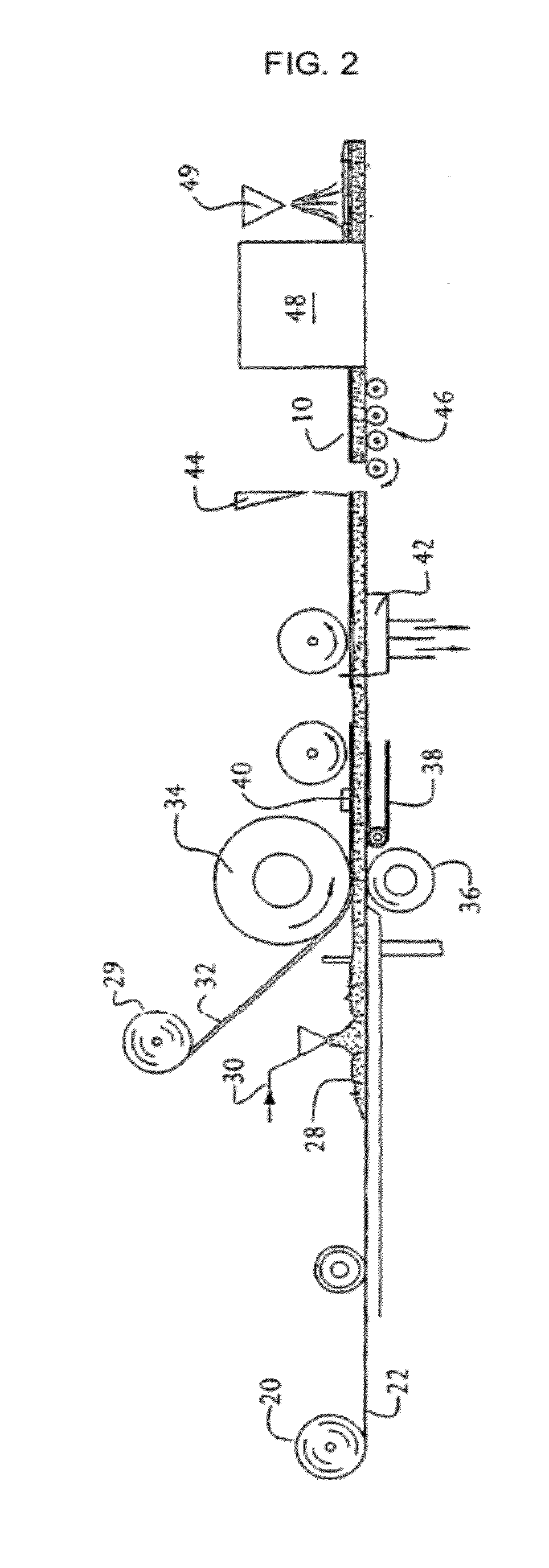

Image

  • Fiberglass mesh scrim reinforced cementitious board system
  • Fiberglass mesh scrim reinforced cementitious board system
  • Fiberglass mesh scrim reinforced cementitious board system

Examples


example 1

[0147]Specific examples of typical cement boards made with a fiberglass mesh scrim made with a conventional G-75 fiberglass yarn available from the St-Gobain Technical Fabrics, which has a yarn fiber density of about 7500 linear yards per one pound of yarn and has a typical mesh grid structure with 8 to 7.5 strands per inch in the longitudinal (machine) and transverse (cross machine) directions compare to an improved fiberglass mesh scrim which is made from a G-37 fiberglass yarn which has also been made by St-Gobain technical Fabrics, which is made from a similarly water and alkali resistant coated fiberglass fabric and mesh constructed but which is thicker in diameter and which has a density of about 3700 linear yards per one pound of fiberglass yarn and which is made into a mesh with 4 to 5 strands per inch e.g. 4.5×4.5 strands per inch, in the longitudinal (machine) and transverse (cross machine) directions, as shown in Table 5, below.

[0148]TABLE 5-As-is and Long Term Flexural S...

example 3

[0157]A number of lab test panels were made from the formulations of TABLE 10 and TABLE 11 (see Example 4) in a mold with the bottom scrim laid in first, followed by pouring the cementitious slurry and then removing excess slurry with a trowel to give a thickness of 0.5″. The top scrim is then placed over the top of the slurry and then the surface is gently finished with a trowel to make sure the top scrim is embedded into the slurry. The samples are sealed and cured at 90° F. / 90% RH for 7 days before the flexural strength and nail pull testing is performed. The slurry formulation used for the lab cast is the same formulation in manufacturing cement panels is used at the plants to evaluate the effect of the use of a wide range of panel density on the nail pull strength obtained with the 4×4 fiberglass mesh scrim of the invention.

[0158]The manufactured cement boards were skin-reinforced using alkali-resistant, polyvinyl chloride (PVC) coated fiberglass mesh embedded in cementitious s...

example 4

Plant Scale Production of Cement Board Made with 4×4 Fiberglass Mesh Scrim of the Present Invention Compared to Cement Board Made with Conventional 8×8 Fiberglass Mesh Scrim

[0169]Since use of more open mesh like the G-37 mesh scrim for the tighter mesh of the conventional G-75 mesh scrim could present a potential problem for nail pull performance, this property was tested on the following plant trial samples of cement board in this Example.

[0170]The following examples illustrates producing lightweight cement boards in a commercial manufacturing process using the improved fiberglass mesh scrim of the invention. The raw materials used included a cementitious reactive powder of Portland cement Type III, class C fly ash, and calcium sulfate dihydrate (landplaster), chemically coated perlite, expanded clay and shale aggregate and added liquids. The liquids, e.g., triethanolamine, were admixtures added as aqueous solutions. In addition, sodium citrate and sulfonated napthalene superplasti...


PUM

PropertyMeasurementUnit
Massaaaaaaaaaa
Lengthaaaaaaaaaa
Densityaaaaaaaaaa

Abstract

A cementitious board system which is reinforced on its opposed surfaces by an improved glass fiber mesh scrim with thicker yarn and larger mesh openings to provide a cementitious board with improved handling properties while retaining tensile strength and long term durability. The fabric is constructed as a mesh of high modulus strands of bundled glass fibers encapsulated by alkali and water resistant material, e.g. a thermoplastic material. The composite fabric also has suitable physical characteristics for embedment within the cement matrix of the panels or boards closely adjacent the opposed faces thereof. The fabric provides a board system with long-lasting, high strength tensile reinforcement and improved handling properties regardless of their spatial orientation during handling. Included as part of the invention are methods for making the reinforced board.

Description

FIELD OF THE INVENTION[0001]The present invention relates generally to cementitious panels or boards, including cement board and cement fiberboard, wherein the cementitious board is reinforced for tensile strength, impact resistance and improved Runnability and field performance through use of an improved fiber mesh scrim.BACKGROUND OF THE INVENTION[0002]The use of reinforced cement panels is well known in industries such as the ceramic tile industry. Generally, cement panels or boards contain a core formed of a cementitious material which may be interposed between two layers of facing material. The facing materials employed typically share the features of high strength, high modulus of elasticity, and light weight to contribute flexural and impact strength to the high compressive strength, but brittle material forming the cementitious core. Typically, the facing material employed with cement panels is fiberglass fibers or fiberglass mesh embedded in the cementitious slurry core. Fi...

Claims


Application Information

Patent Timeline
IPC IPC(8): E04C2/06B32B13/02B32B37/24
CPCB28B19/0092Y10T428/24785C04B14/185C04B28/04C04B2111/00629E04C2/06B28B23/0006E04C2/049B32B2262/101B32B2260/044B32B2260/023B32B2260/021B32B13/14C04B14/06C04B14/12C04B14/14C04B14/16C04B16/08C04B18/08C04B18/141C04B38/10C04B2103/0079C04B2103/12C04B2103/22C04B2103/302C04B2103/304C04B2103/44C04B2103/54C04B2103/58C04B20/1003Y10T442/10Y02W30/91B32B13/02B32B37/24
Inventor DUBEY, ASHISHPENG, YANFEI
Owner UNITED STATES GYPSUM CO
Learn More