
Retardation film based on optically aligned liquid crystalline polyimide and optical device

Inactive Publication Date: 2012-05-31
JNC CORP +1
View PDF9 Cites 29 Cited by
  • Summary
  • Abstract
  • Description
  • Claims
  • Application Information

AI Technical Summary

Benefits of technology

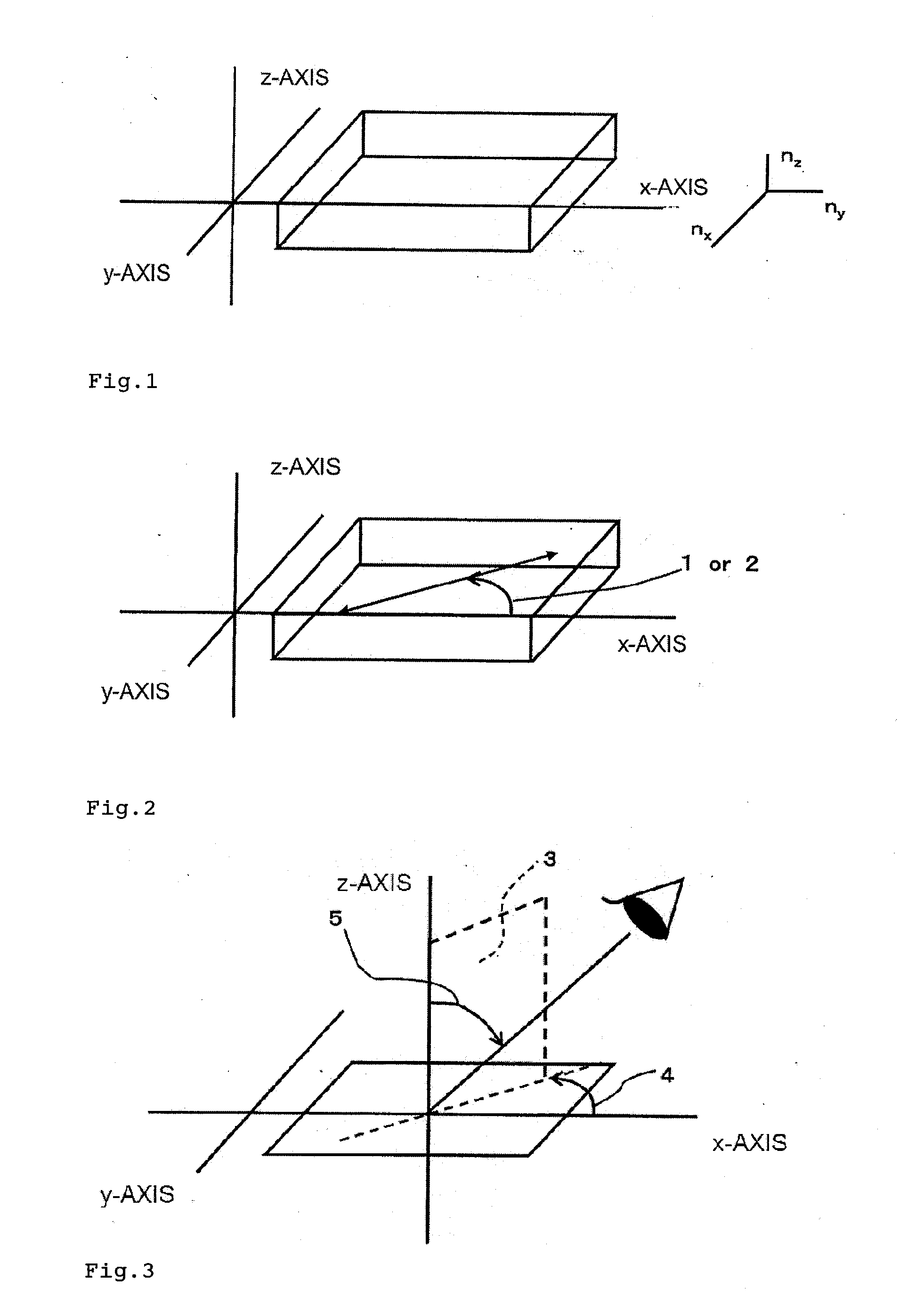
[0014]The inventors of the present invention have found a specific structure of a polyamic acid that expresses thermotropic liquid crystallinity by being heated and imidated, and has optical alignment property, and have found that a thin film obtained by optically aligning, heating, and imidating the polyamic acid in a coating film thereof can be utilized as a retardation film as well by virtue of large optical anisotropy obtained by the liquid crystallinity expressed by the imidation. Further, the inventors have found that optical characteristics in the thin film as a retardation film such as the axial angle of an optical axis and the magnitude of a retardation can be controlled by irradiating the coating film with light while controlling the polarization state, and irradiation energy intensity, of light to be optically aligned. Thus, the inventors have completed the present invention.
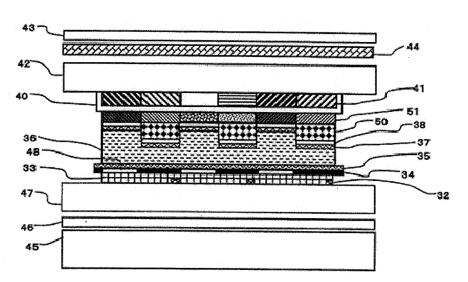
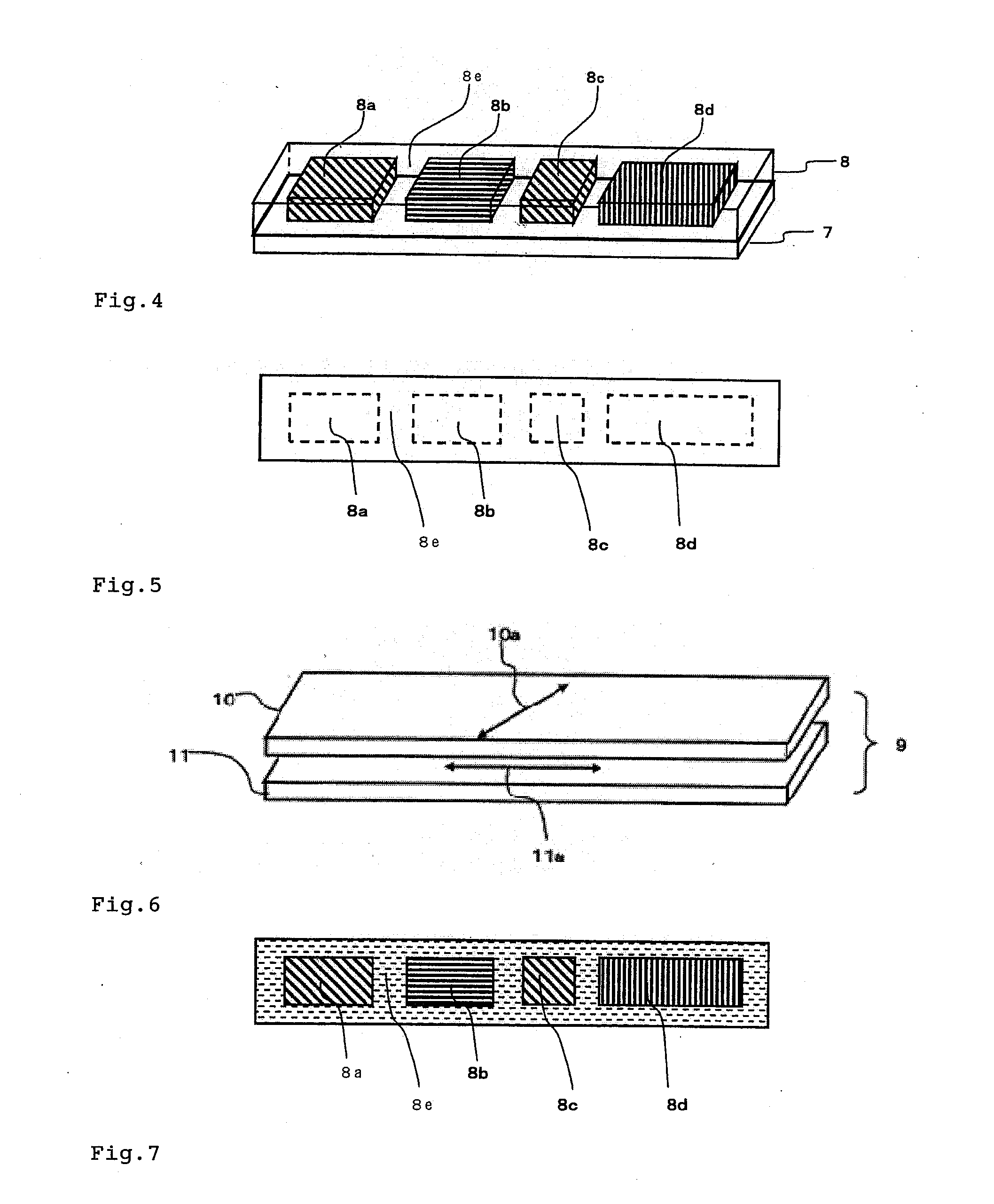
[0038]According to the present invention, optical characteristics, that is, the orientation (axial angle) of an optical axis and the magnitude of a retardation can be adjusted depending on the polarization state, irradiation energy intensity, and the like of light to be applied to a film of a polyamic acid before being heated and imidated. In addition, a retardation film having high heat resistance peculiar to a polyimide is obtained. Therefore, the present invention can provide a technology by which a retardation film in which regions different from each other in one or both of the axial angle of an optical axis and the magnitude of a retardation are patterned can be produced with additionally small numbers of members and steps. Further, the present invention can provide each of an optical device and a liquid crystal display device each using the patterned retardation film as well with additionally small numbers of members and steps.

Problems solved by technology

However, it is difficult to obtain the patterned retardation film by the approach.
In addition, the production of a retardation film in which both an optical axis and a retardation are patterned can be achieved by combining the technologies of Patent Documents 1 and 2, but it is apparent that a production step becomes additionally complicated.
However, the magnitude of the retardation differs from an ideal one at a wavelength except λm, and hence a liquid crystal display apparatus mounted with the film cannot obtain sufficiently satisfactory values for characteristics concerning the performance of the display apparatus such as a contrast ratio.

Method used


Image

  • Retardation film based on optically aligned liquid crystalline polyimide and optical device
  • Retardation film based on optically aligned liquid crystalline polyimide and optical device
  • Retardation film based on optically aligned liquid crystalline polyimide and optical device

Examples


example 1

[0252]

[0253]A mixture of 4-bromophthalic acid diethyl ester (50 g, 166 mmol), 1,7-octadiyne (8.7 g, 82 mmol), dichlorotriphenylphosphinepalladium(II) (290 mg, 0.41 mmol), and copper iodide (158 mmol, 0.83 mmol) was refluxed in a stream of nitrogen in triethylamine (200 mL) for 4 hours. After the completion of the reaction, toluene (500 mL) and pure water (500 mL) were added to perform extraction. The organic phase was washed with pure water (300 mL) once, and was then dried with anhydrous magnesium sulfate. The resultant organic phase was filtrated and the solvent was removed by distillation under reduced pressure. Thus, 1,4-bis(3,4-dicarboxyphenyl)ethynylbutane tetraethyl ester as a target product was obtained in an amount of 42 g in 95% yield. The compound was directly used in the next reaction without being purified.

[0254]5% Pd / C (2.1 g) was added to 1,4-bis(3,4-dicarboxyphenyl)ethynylbutane tetraethyl ester (42 g, 77 mmol), and then the mixture was subjected to a hydrogenation r...

example 2

[0267]A composition formed of 82.2 wt % of Compound (P-1) below, 4.8 wt % of Compound (P-2) below, 9.7 wt % of Compound (P-3) below, and 3.3 wt % of Compound (P-4) below was defined as a (MIX1). A CPI-110P (San-Apro Ltd.) having a weight ratio of 0.030 was added to the (MIX1), and then cyclopentanone having a weight ratio of 2.333 was added to the mixture. Thus, a cyclopentanone solution (B-1) having a solute concentration of 30 wt % was obtained. It should be noted that Compound (P-1) was synthesized by a method described in Macromolecules, 1993, 26(6), 244. In addition, Compound (P-2) and Compound (P-3) were each synthesized by a method described in Japanese Patent Application Laid-open No. 2005-60373. Further, Compound (P-4) was synthesized by a method described in Japanese Patent Application Laid-open No. 2005-263778.

[0268]

[0269]The solution (B-1) was applied to the retardation film 1 with a spinner under the conditions of 1,500 rpm and 15 seconds. Further, the resultant coating...

example 3

[0270]

[0271]A composition formed of 75 wt % of Compound (P-5) below and 25 wt % of Compound (P-6) below was defined as a (MIX2). An IRGACURE 907 (Ciba Japan K.K.) having a weight ratio of 0.03 was added to the (MIX2), and then cyclopentanone having a weight ratio of 2.333 was added to the mixture. Thus, a cyclopentanone solution (B-2) having a solute concentration of 30 wt % was obtained. It should be noted that Compound (P-5) was synthesized by a method described in Japanese Patent Application Laid-open No. 2006-307150. In addition, Compound (P-6) was synthesized by a method described in Macromolecules, 1990, 23(17), 3938.

[0272]

(Retardation Film (I))

[0273]A retardation film (I) was produced by applying the solution (A-2) to a glass substrate same as the production of the retardation film 1 of Example 1. The irradiation energy of polarized ultraviolet light to be applied to a film of the solution (A-2) before baking was set to zero. The resultant retardation film (I) had a thickness...


PUM


Abstract

Provided is a technology by which a retardation film in which regions different from each other in one or both of optical characteristics, i.e., an optical axis and a retardation are patterned can be produced with an additionally small load. The retardation film is formed of a liquid crystalline polyimide film having a photoreactive group. Further provided is an optical device and a liquid crystal display apparatus each having the retardation film.

Description

TECHNICAL FIELD[0001]The present invention relates to a retardation film produced by using a liquid crystalline polyimide having a photoreactive group in which a plurality of regions different from each other in optical characteristic, i.e., an optical axis or a retardation are patterned, and an optical device and a liquid crystal display apparatus each having the retardation film.BACKGROUND ART[0002]Retardation films have been utilized in optical devices such as a pickup optical system and an optical device for anti-counterfeit in addition to a liquid crystal display apparatus because each of the films has a function of transforming a polarization state before the passing of the film into another different polarization state by virtue of its optical characteristics such as the magnitude of its retardation and the axial angle of its optical axis.[0003]Further, the patterning of each of the retardation films by changing the optical characteristics such as the magnitude of the retarda...

Claims


Application Information

Patent Timeline
IPC IPC(8): G02F1/1335G02F1/13
CPCG02F1/13363G02B5/3083
Inventor SAIGUSA, KAZUHIKOTAMURA, NORIO
Owner JNC CORP
Learn More