
Tmr device with improved mgo barrier

Active Publication Date: 2012-05-24
HEADWAY TECH INC
View PDF1 Cites 24 Cited by
  • Summary
  • Abstract
  • Description
  • Claims
  • Application Information

AI Technical Summary

Benefits of technology

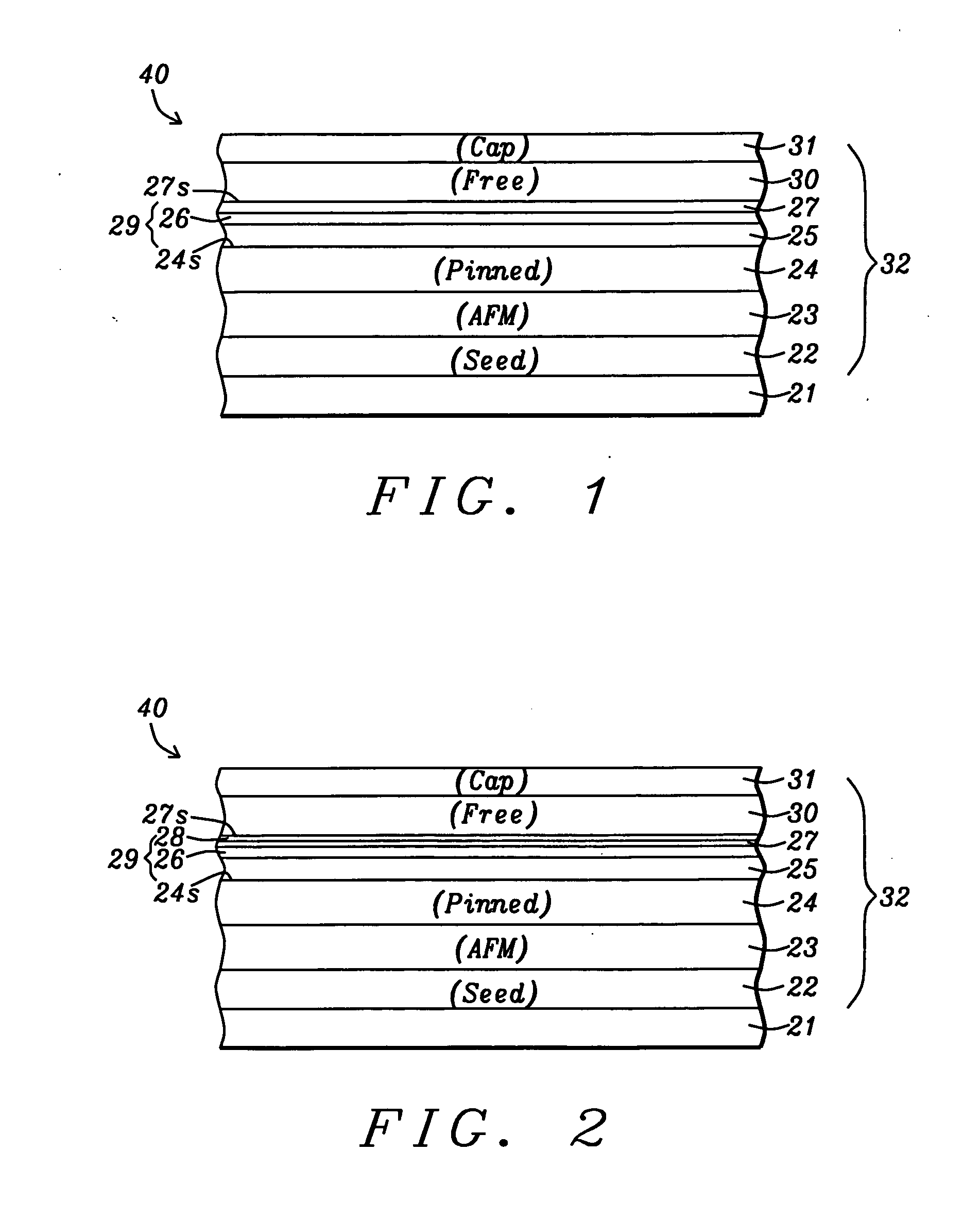
[0013]In one aspect, the TMR sensor may have a configuration represented by seed layer / AFM layer / pinned layer / tunnel barrier / free layer / cap layer wherein the pinned layer has a synthetic anti-ferromagnetic (SyAF) structure comprised of an AP2 / coupling / AP1 configuration in which the coupling layer is Ru. Typically, the TMR stack of layers including the multiple M layers in the tunnel barrier are laid down in a sputter deposition system. A key feature is that all of the M layers except for the last metal layer deposited are oxidized with a natural oxidation (NOX) method. Furthermore, the pinned layer in a bottom spin valve configuration may be treated with Ar plasma or a light oxidation prior to depositing the first M layer in order to improve the interface between the pinned layer and first M layer. Also, the uppermost M layer may be treated with Ar plasma, a low dose of oxygen, an Ar / O2 mixture, or other inert gas mixtures before the free layer is sputter deposited. One purpose of these treatments is to minimize metal inter-diffusion at the interface between free layer and tunnel barrier. Another purpose is to form better bonding between Mg and oxygen before depositing the free layer. A subsequent anneal step essentially forms a uniform metal oxide layer. The aforementioned plasma or gas treatments are advantageous in forming a smoother and more uniform tunnel barrier layer and sharper interfaces that may help to improve dR / R and / or other device performance.

Problems solved by technology

However, the uppermost metal layer is not treated with NOX.

Method used


Image

  • Tmr device with improved mgo barrier
  • Tmr device with improved mgo barrier
  • Tmr device with improved mgo barrier

Examples


second embodiment

[0026]The M1 layer has a greater thickness than other M layers, and preferably greater than 4 Angstroms in order to generate a continuous metal layer free of pinholes before the first MOX layer is formed. The formation of at least three MOX layers provides an advantage over a bilayer scheme in that a more uniform tunnel barrier is produced. It should be understood that as a metal layer thickness increases, a stronger NOX dose (longer oxidation time and / or higher oxygen pressure) is required to oxidize the layer. Therefore, according to one embodiment of the present invention where relative thickness is in the order M1>M2>M3, and M3 becomes fully oxidized during an annealing step, the NOX dose for the M1 layer is higher than for M2. In a second embodiment wherein relative thickness is on the order M1>M2>M3, M4, and M4 becomes fully oxidized during a subsequent annealing step, the NOX dose for M1 is higher than for M2, and M2 NOX dose is higher than that for M3. As described in relate...


PUM


Abstract

A method of forming a high performance magnetic tunnel junction (MTJ) is disclosed wherein the tunnel barrier includes at least three metal oxide layers. The tunnel barrier stack is partially built by depositing a first metal layer, performing a natural oxidation (NOX) process, depositing a second metal layer, and performing a second NOX process to give a MOX1 / MOX2 configuration. An uppermost metal layer on the MOX2 layer is not oxidized until after the MTJ stack is completely formed and an annealing process is performed to drive unreacted oxygen in the MOX1 and MOX2 layers into the uppermost metal layer. In an alternative embodiment, a plurality of metal oxide layers is formed on the MOX1 layer before the uppermost metal layer is deposited. The resulting MTJ stack has an ultralow RA around 1 ohm-μm2 and maintains a high magnetoresistive ratio characteristic of a single metal oxide tunnel barrier layer.

Description

RELATED PATENT APPLICATION[0001]This application is related to U.S. Patent Application Publication 2007 / 0111332; Ser. No. 11 / 280,523, filed on Nov. 16, 2005; assigned to a common assignee and herein incorporated by reference in its entirety.FIELD OF THE INVENTION[0002]The invention relates to a high performance tunneling magnetoresistive (TMR) sensor in a recording head and a method for making the same, and in particular, to a method of forming a tunnel barrier layer between a pinned layer and free layer that improves reliability, decreases the resistance x area (RA) value to about 1 ohm-cm2 or less while maintaining a high magnetoresistive (MR) ratio.BACKGROUND OF THE INVENTION[0003]A TMR sensor serves as a memory element in Magnetic Random Access Memory (MRAM) devices and in magnetic read heads, and typically includes a stack of layers with a configuration in which two ferromagnetic layers are separated by a thin non-magnetic dielectric layer. In a magnetic read head, the TMR sens...

Claims


Application Information

Patent Timeline
IPC IPC(8): H01F1/047
CPCH01F41/307B82Y40/00H01L43/12G11C11/161H10N50/01
Inventor ZHAO, TONGWANG, HUI-CHUANLI, MINZHANG, KUNLIANG
Owner HEADWAY TECH INC
Learn More