
Bilayer protection coating and related method

a protection coating and bilayer technology, applied in the direction of machines/engines, superimposed coating processes, soldering devices, etc., can solve the problem of reducing the ability of the outer layer to fight oxidation

Inactive Publication Date: 2012-04-12
GENERAL ELECTRIC CO
View PDF4 Cites 0 Cited by
  • Summary
  • Abstract
  • Description
  • Claims
  • Application Information

AI Technical Summary

Benefits of technology

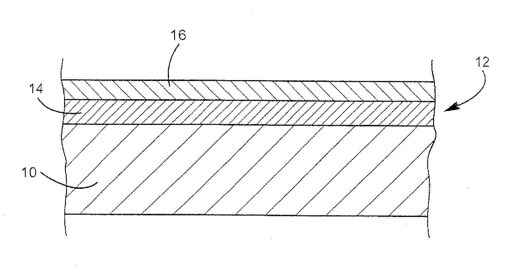
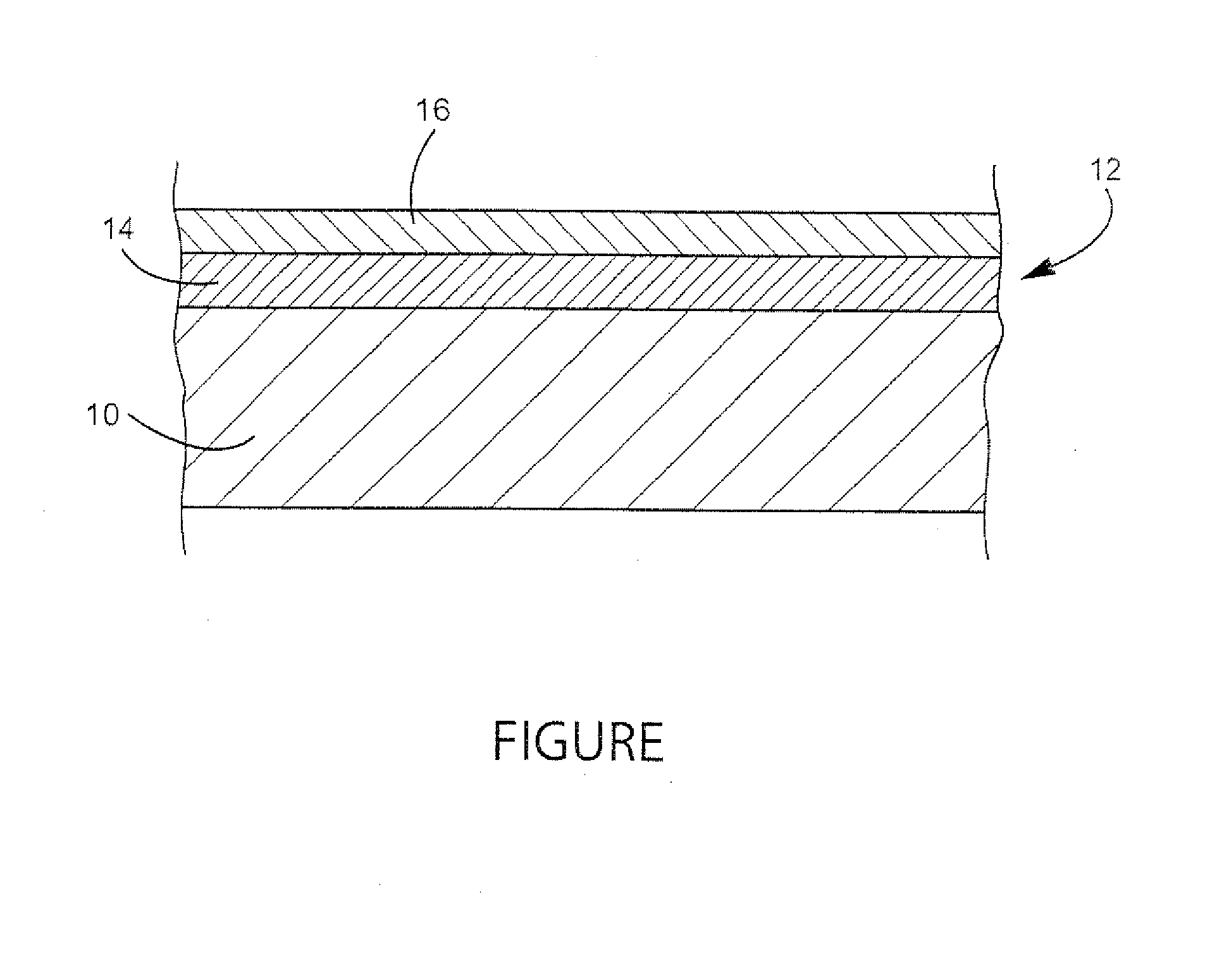
[0004]In an exemplary but non-limiting embodiment, there is described herein a bilayer coating comprised of an inner layer of diffused PtAl (or PdAl), and an outer oxidation-resistant layer that is applied over a nickel or cobalt-based superalloy substrate. This arrangement protects the base superalloy component from oxidation and corrosion as described further herein.
[0006]The addition of an inner PtAl (or PdAl) diffused layer, between the outer oxidation-resistant layer and the Ni or Co-based superalloy substrate, serves to slow diffusion of aluminum from the outer oxidation-resistant layer into the nickel or cobalt-based substrate. This is important because diffusion of aluminum from the outer oxidation-resistant layer into the substrate reduces the ability of the outer layer to fight oxidation. By slowing the diffusion of aluminum into the substrate or superalloy base, the rate of oxidation and corrosion of the substrate is slowed, thereby increasing part life.

Problems solved by technology

This is important because diffusion of aluminum from the outer oxidation-resistant layer into the substrate reduces the ability of the outer layer to fight oxidation.

Method used


Image

  • Bilayer protection coating and related method
  • Bilayer protection coating and related method

Examples


Embodiment Construction

[0011]With reference to the single drawing figure, the substrate 10 may be part of any gas turbine component, and particularly a hot gas path component subject to extreme temperature environments. The component substrate in the exemplary embodiment is a nickel or cobalt-based superalloy typically used for such components. A bilayer coating 12 is applied over the substrate 10 to provide protection from damage due to oxidation and corrosion.

[0012]A first inner layer or bond coat 14 of the coating 12 may be comprised of platinum (or palladium) aluminide (PtAl or PdAl), i.e., a PtAl or PdAl diffused aluminide coating layer. The platinum (or palladium) component is deposited first by any suitable process such as electroplating, paint or slurry methods. The aluminum component of the inner layer 14 is preferably applied in aluminide form, by vapor phase (above the pack vapor or chemical vapor deposition (CVD)) techniques, or pack powder techniques. In other words, the first inner layer may...


PUM

PropertyMeasurementUnit
thicknessaaaaaaaaaa
corrosionaaaaaaaaaa
oxidation resistanceaaaaaaaaaa

Abstract

A turbine component having a protective bilayer coating thereon comprising: a superalloy substrate; and a bilayer protective coating applied to the substrate wherein the bilayer protective coating comprises a first inner layer of platinum and aluminum; and a second outer oxidation-resistant layer applied over the first inner layer, the second outer layer comprising an MCrAlX alloy where M is selected from Fe, Ni and Co, and where X is yttrium or another rare earth element. A method of improving oxidation resistance of a Ni or Co-based superalloy turbine component comprising: depositing a bilayer protective coating on a turbine component by depositing a first inner platinum-aluminum layer on a surface of the turbine component; and depositing a second outer layer comprising an MCrAlX alloy over the first inner layer, wherein M is a metal selected from Fe, Ni and Co, and X is yttrium or another rare earth element.

Description

RELATED APPLICATIONS[0001]This application is a continuation of U.S. application Ser. No. 11 / 902,423 filed Sep. 21, 2007, the entirety of which is incorporated herein by reference.BACKGROUND OF THE INVENTION[0002]This invention relates to gas turbine engine technology generally, and specifically to protective coatings for turbine components exposed to harsh conditions.[0003]Gas turbine engines run in extreme temperature environments. The nickel and cobalt-based superalloys of which many of the hot gas path components are composed, are exposed to harsh conditions where either oxidation or corrosion damage may penetrate into the superalloy substrate. Components damaged in this manner must be removed and repaired before returning the components to service. The repair process, however, reduces the wall thickness of the part and ultimately the life of the component.BRIEF DESCRIPTION OF THE INVENTION[0004]In an exemplary but non-limiting embodiment, there is described herein a bilayer coa...

Claims


Application Information

Patent Timeline
Patent Type & Authority Applications(United States)
IPC IPC(8): B32B15/01
CPCC23C4/02C23C10/60F01D5/288C23C28/022C23C28/023Y10T428/12986F05D2300/121F05D2300/143F05D2300/15Y10T428/12771Y10T428/1275C23C28/028
Inventor BUCCI, DAVID V.MOREY, KATHLEEN B.
Owner GENERAL ELECTRIC CO
Learn More