Spin torque oscillator and magnetic recording head and magnetic recording device mounted with the spin torque oscillator
a spin torque oscillator and spin torque technology, which is applied in the direction of magnetic recording heads, instruments, data recording, etc., can solve the problems of difficult to develop large perpendicular magnetic anisotropy, and achieve high oscillation frequency, large high-frequency magnetic field intensity, and large spin torque efficiency
- Summary
- Abstract
- Description
- Claims
- Application Information
AI Technical Summary
Benefits of technology
Problems solved by technology
Method used
Image
Examples
first embodiment
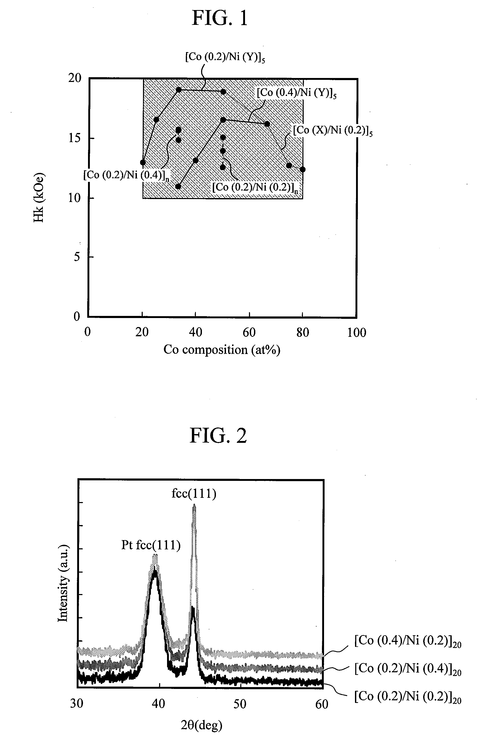
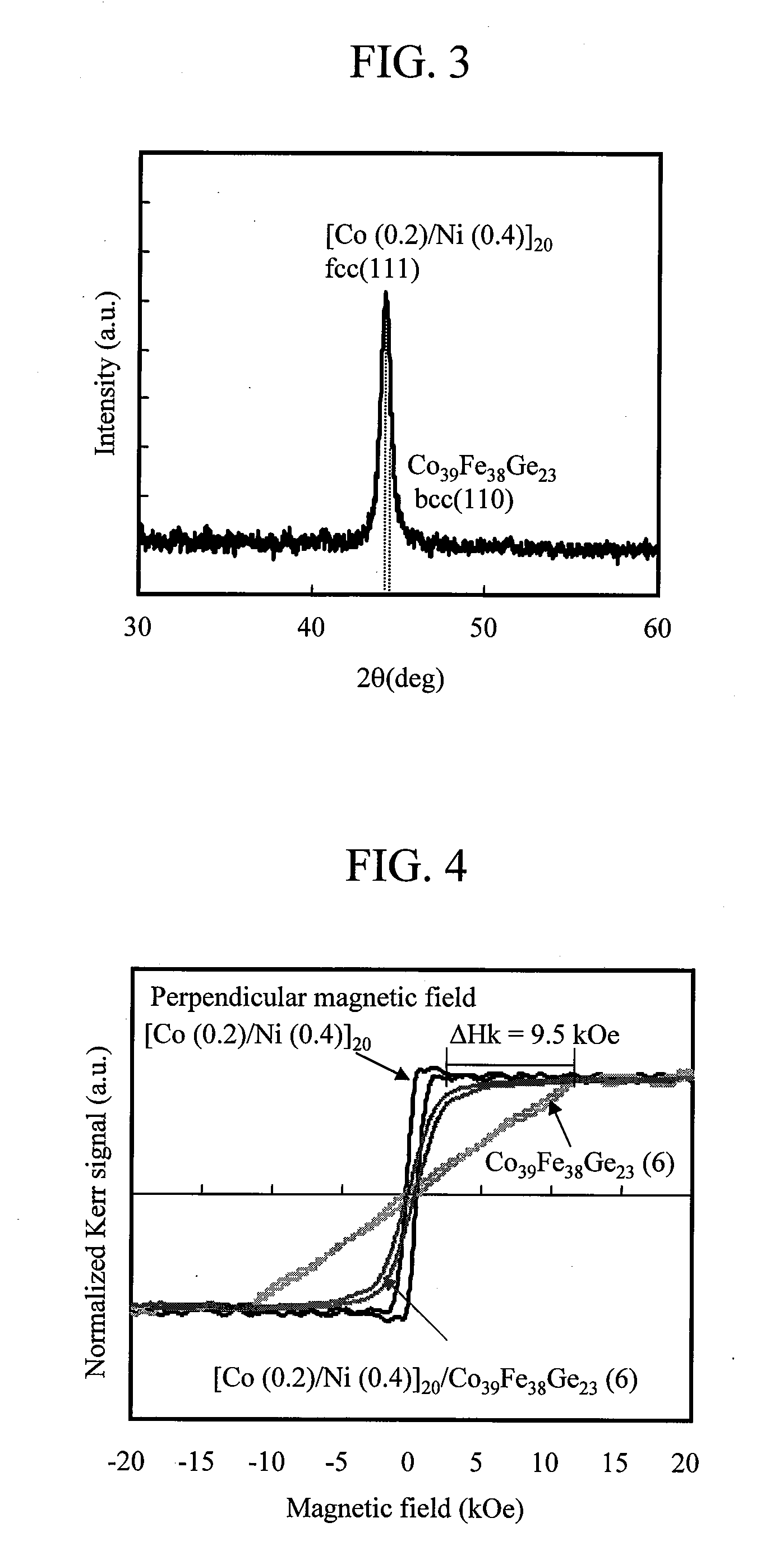
[0027]FIG. 1 is a diagram showing a result obtained by evaluating, concerning various configurations of a [Co(0.2 to 0.8) / Ni(0.2 to 0.8)]n=5-20 / Pt(5) / Ta(3) / glass substrate, an anisotropic magnetic field Hk from a magnetization curve using a vibrating sample magnetometer (VSM) after applying heat treatment to a solid film at 250° C. for three hours. Numerical values in parentheses are film thickness indicated in an nm unit. “n” represents the number of laminations of [Co / Ni]. A Co composition on the abscissa is a ratio of Co and Ni formed as a film converted into at %. It is seen from this result that, when an average composition of Co in a magnetic film is in a composition range of 20 at %≦CO≦30 at % and the number of laminations is 5≦n≦20, at least [Co(0.2 to 0.8) / Ni((0.2 to 0.8)]n=5-20 is a perpendicular magnetization film having Hk≦10 kOe. When [Co / Ni]n is considered an integral magnetic layer, the average composition is defined by a ratio of Co in the magnetic layer.
[0028]In FIG...
second embodiment
[0035]A specific configuration example of the spin torque oscillator including the first magnetic layer and the second magnetic layer described in the first embodiment is shown in FIG. 5.
[0036]FIG. 5 is a configuration obtained by laminating a magnetization fixed layer 4, a nonmagnetic intermediate layer 3, a first magnetic layer 1, a second magnetic layer 2, a cap layer 5, and an trailing shield 7 in order on a main pole 6. As a material of the main pole 6 in this configuration, it is desirable to use a high Bs material based on CoFe in order to obtain large recording magnetic field intensity. The magnetization fixed layer 4 laminated on the main pole 6 is a spin torque source. Therefore, it is necessary to suppress fluctuation in magnetization due to spin torque. Alloys and multilayer films such as CoPt, CoCrPt, CoPd, FePt, CoFePd, TbFeCo, and Co / Ni having perpendicular magnetic anisotropy can be used. A magnetization direction can be fixed perpendicular to a film surface using a ...
third embodiment
[0043]In FIG. 7, another specific configuration example of the spin torque oscillator including the first magnetic layer and the second magnetic layer explained in the first embodiment is shown.
[0044]FIG. 7 is a configuration in which the second magnetic layer 2, the first magnetic layer 1, the non-magnetic intermediate layer 3, the magnetization fixed layer 4, the cap layer 5, and the trailing shield 7 are laminated in order on the main pole 6. As a material of the main pole 6 of this configuration, it is desirable to use a high Bs material based on CoFe in order to obtain large recording magnetic field intensity. As the second magnetic layer 2 laminated on the main pole 6, an alloy having perpendicular magnetic anisotropy added with Pt or Pd as a third element besides Co and Ni or a structure having perpendicular magnetic anisotropy including a multilayer film can be used.
[0045]In this case, since the material of the main pole 6 has a bcc crystal structure based on CoFe, a magneti...
PUM
 Abstract
Description
Claims
Application Information
 - R&D
- Intellectual Property
- Life Sciences
- Materials
- Tech Scout
- Unparalleled Data Quality
- Higher Quality Content
- 60% Fewer Hallucinations
Browse by: Latest US Patents, China's latest patents, Technical Efficacy Thesaurus, Application Domain, Technology Topic, Popular Technical Reports.
© 2025 PatSnap. All rights reserved.Legal|Privacy policy|Modern Slavery Act Transparency Statement|Sitemap|About US| Contact US: help@patsnap.com


