Colloidal sphere templates and sphere-templated porous materials
a porous material and template technology, applied in the field of ##lithiumion anode materials, can solve the problems of lithium-metal alloy systems with very poor cycling characteristics, affecting the application of rechargeable battery systems, and reducing research in this field, so as to achieve the effect of reducing the specific charge capacity and charge/discharge rate, cycling efficiency, and reducing the cracking of dried films
- Summary
- Abstract
- Description
- Claims
- Application Information
AI Technical Summary
Benefits of technology
Problems solved by technology
Method used
Image
Examples
example1
Vertical Deposition Template Formation—Single Modal Size Distribution
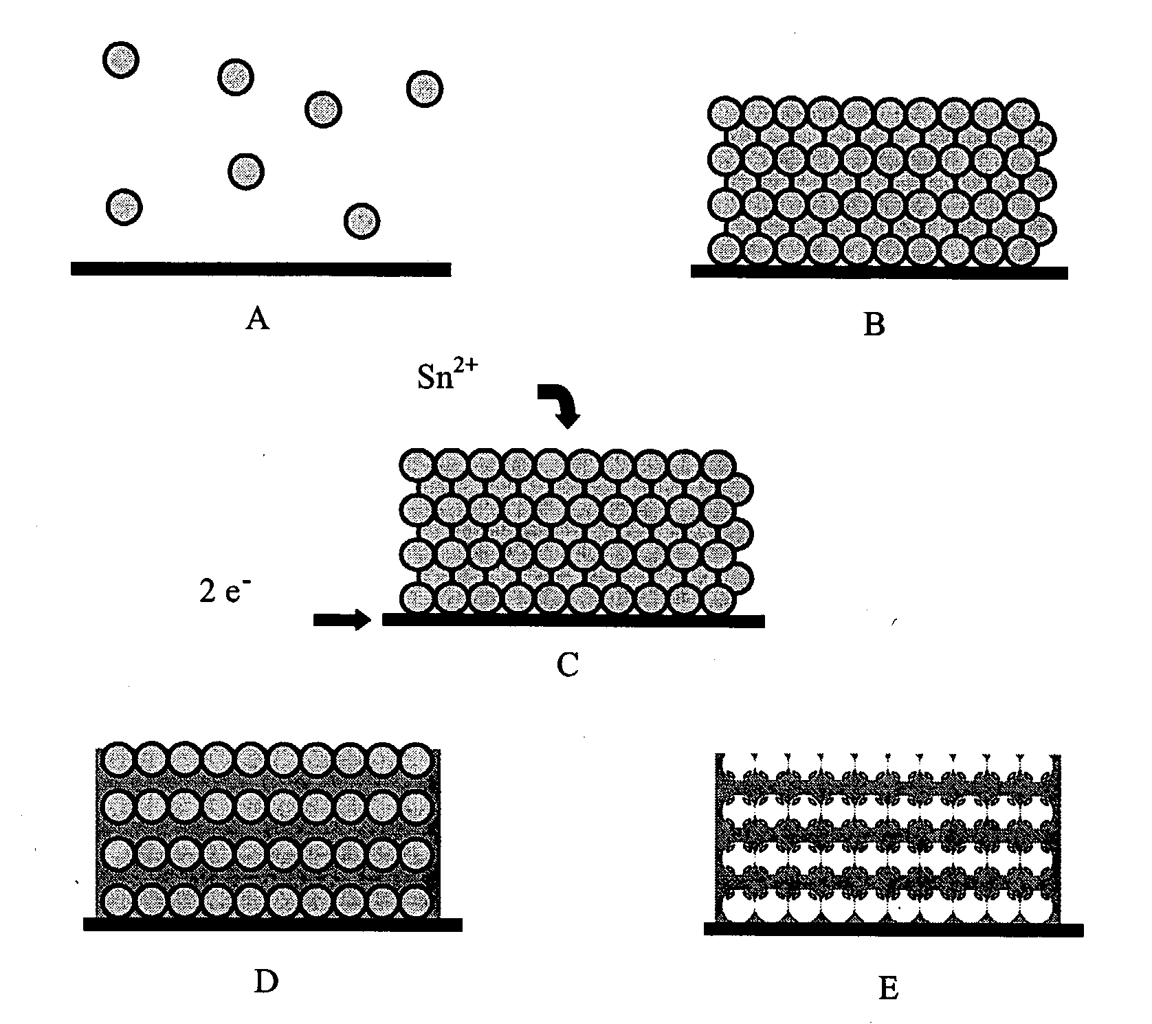
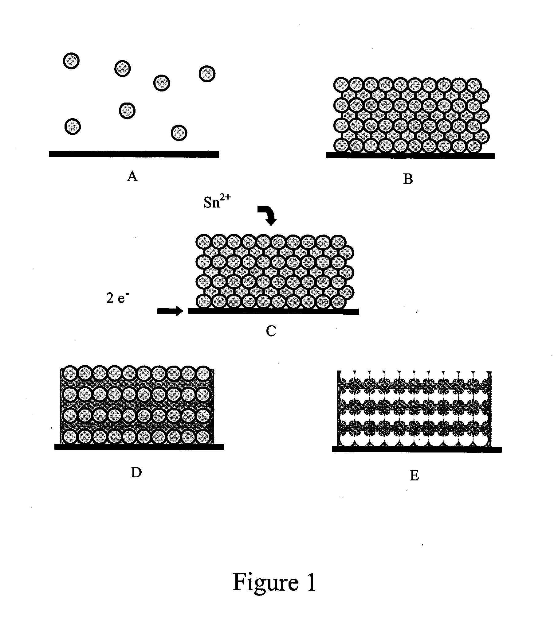
[0042]Conductive substrates for use in vertical deposition experiments were prepared by thoroughly cleaning laboratory glass slides (2×3 inches), then depositing 100 Å of Ti followed by 500 Å of Pt or Au using electron beam evaporation. Both Pt and Au were used in different samples. A plastic mask was fashioned out of a strip of Teflon, such that only certain areas of the slide were exposed to the conductive metal. These slides were cut into smaller strips for use as substrates. Strips of indium tin oxide (ITO) coated glass, which were cut to about 1 cm wide, were also used as substrates after cleaning with isopropanol, dilute HCl, and deionized (DI) water.
[0043]Vertical deposition was carried out by suspending substrates in vials containing dispersions of polystyrene spheres and allowing the solvent to evaporate. Methanol having a concentration of about 98-100 volume % was used as the solvent to prepare dispersion...
example2
Vertical Deposition Template Formation—Multi-Modal Size Distributions
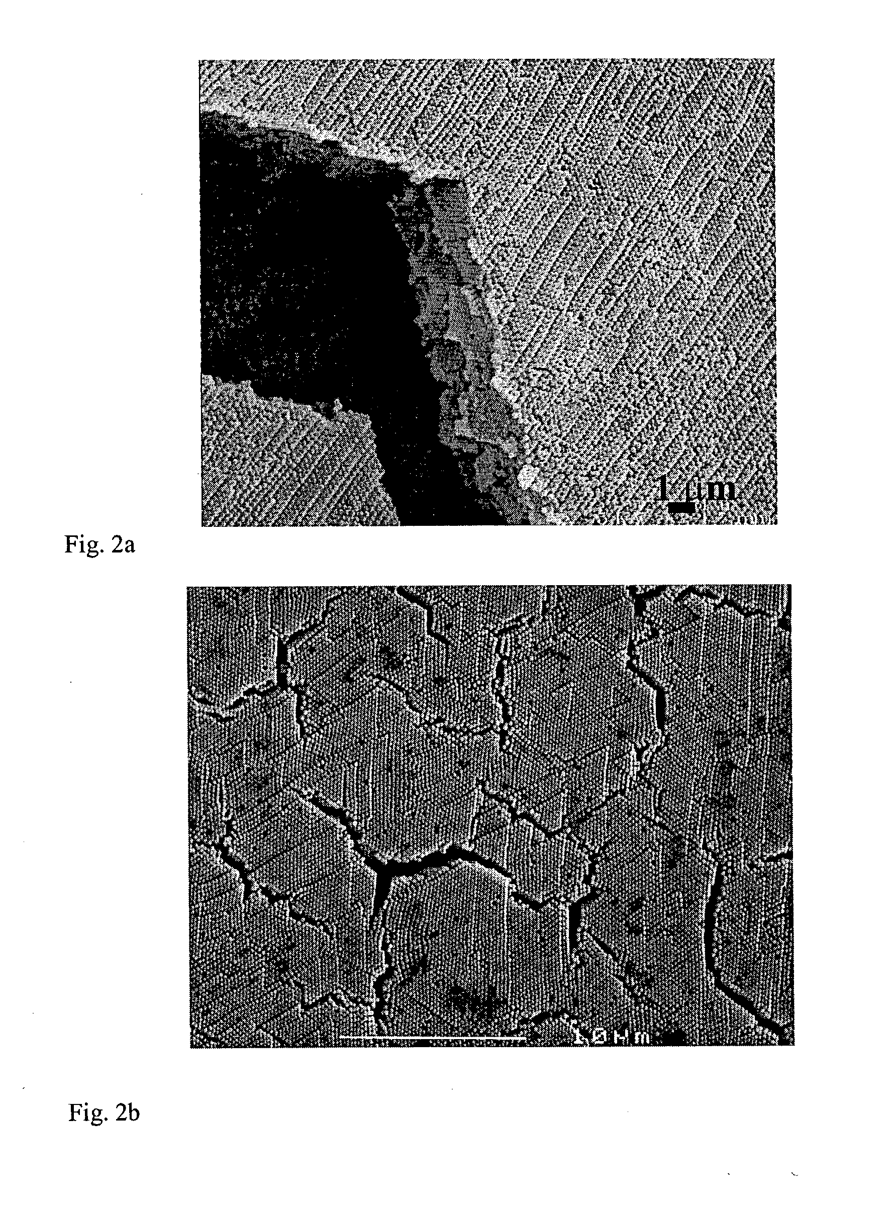
[0050]Templates containing a 1:1 mass ratio of about 250:110 nm diameter (negatively charged) polystyrene spheres were prepared from dispersions ranging from about 0.05 to 0.5 wt. %. The thickness, sphere arrangement, and degree of cracking were assessed by SEM. FIGS. 7A-F are SEM images demonstrating the critical thickness for cracking using the vertical deposition method with polystyrene spheres, which was found to lie between about 0.1 and 0.2%, corresponding to a thickness of about 2.2 microns. (FIG. 7A) 60 nm spheres, 0.10 wt. % dispersion; (FIGS. 7B and C) 60 nm spheres, 0.05 wt. % dispersion; (FIG. 7D) 1:1 ratio of 260:110 nm spheres, 0.20 wt. % dispersion; (FIG. 7E) 1:1 ratio of 260:110 nm spheres, 0.10 wt. % dispersion (FIG. 7F) a higher magnification SEM image of FIG. 7e.
[0051]FIGS. 8a-b illustrate a typical cross-section SEM micrograph showing that an interpenetrating network of void space remained in w...
example 3
“Painting” Template Formation
[0053]A disadvantage of the vertical deposition method is that only a relatively small fraction of the polystyrene spheres used to prepare each dispersion actually contributes to the film. The formation of aggregated particles precludes the reuse of these slurries. Also, templates obtained by this method are generally very thin (less than 3 μm). Thicker templates that lead to thicker porous tin films are desirable in the fabrication of commercially useful battery anodes (e.g., 20-30 μm). Porous tin films of 3 microns thickness will have anode mass of less than 1 mg, making accurate measurement of anode capacity difficult.
[0054]For these reasons, the present invention also provides a method of template formation that does not waste large quantities of spheres and that reliably produces thick films of high quality. The method of spreading a small volume of a concentrated sphere dispersion (e.g., about 8 wt. %) onto the horizontal substrate and allowing the...
PUM
| Property | Measurement | Unit |
|---|---|---|
| mean diameter | aaaaa | aaaaa |
| diameter | aaaaa | aaaaa |
| volume % | aaaaa | aaaaa |
Abstract
Description
Claims
Application Information
 - R&D
- Intellectual Property
- Life Sciences
- Materials
- Tech Scout
- Unparalleled Data Quality
- Higher Quality Content
- 60% Fewer Hallucinations
Browse by: Latest US Patents, China's latest patents, Technical Efficacy Thesaurus, Application Domain, Technology Topic, Popular Technical Reports.
© 2025 PatSnap. All rights reserved.Legal|Privacy policy|Modern Slavery Act Transparency Statement|Sitemap|About US| Contact US: help@patsnap.com


