Logic circuit and semiconductor device
a logic circuit and semiconductor technology, applied in the field of logic circuits, can solve the problems of static power consumption due to leakage current cannot be reduced, power consumption cannot be reduced, power consumption, etc., and achieve the effects of reducing the standby power of logic circuits, reducing the concentration of hydrogen, and reducing the leakage current of transistors
- Summary
- Abstract
- Description
- Claims
- Application Information
AI Technical Summary
Benefits of technology
Problems solved by technology
Method used
Image
Examples
embodiment 1
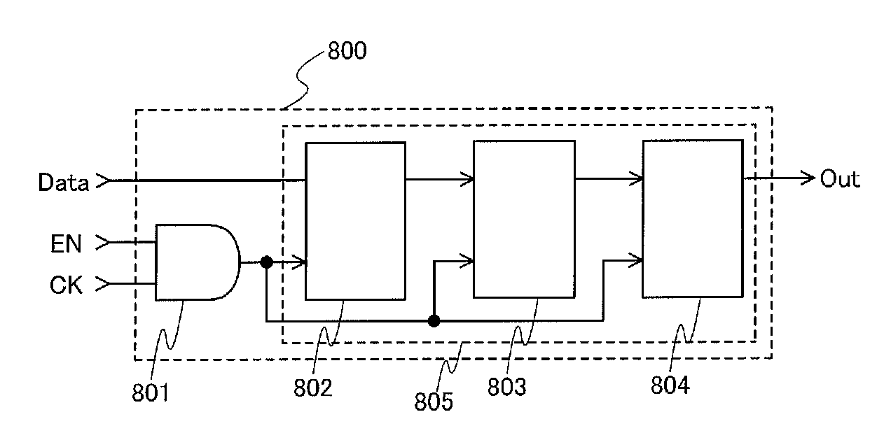
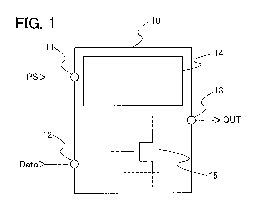
[0047]In this embodiment, an example of a logic circuit where clock gating is performed will be described. Specifically, an example of a logic circuit having a period during which a clock signal is input and a period during which a clock signal is not input and performing arithmetic processing with use of the clock signal will be described with reference to FIG. 1.
[0048]A logic circuit 10 shown in FIG. 1 includes a first input terminal 11 electrically connected to a wiring through which a pulse signal (PS) is supplied (hereinafter, also referred to as a pulse signal line), a second input terminal 12 electrically connected to a wiring through which a data signal (Data) is supplied (hereinafter, also referred to as a data signal line), and an output terminal 13. The logic circuit 10 has a period during which a clock signal (CK) is supplied through the pulse signal line and a period during which a clock signal is not supplied. That is, the logic circuit shown in FIG. 1 is a logic circu...
embodiment 2
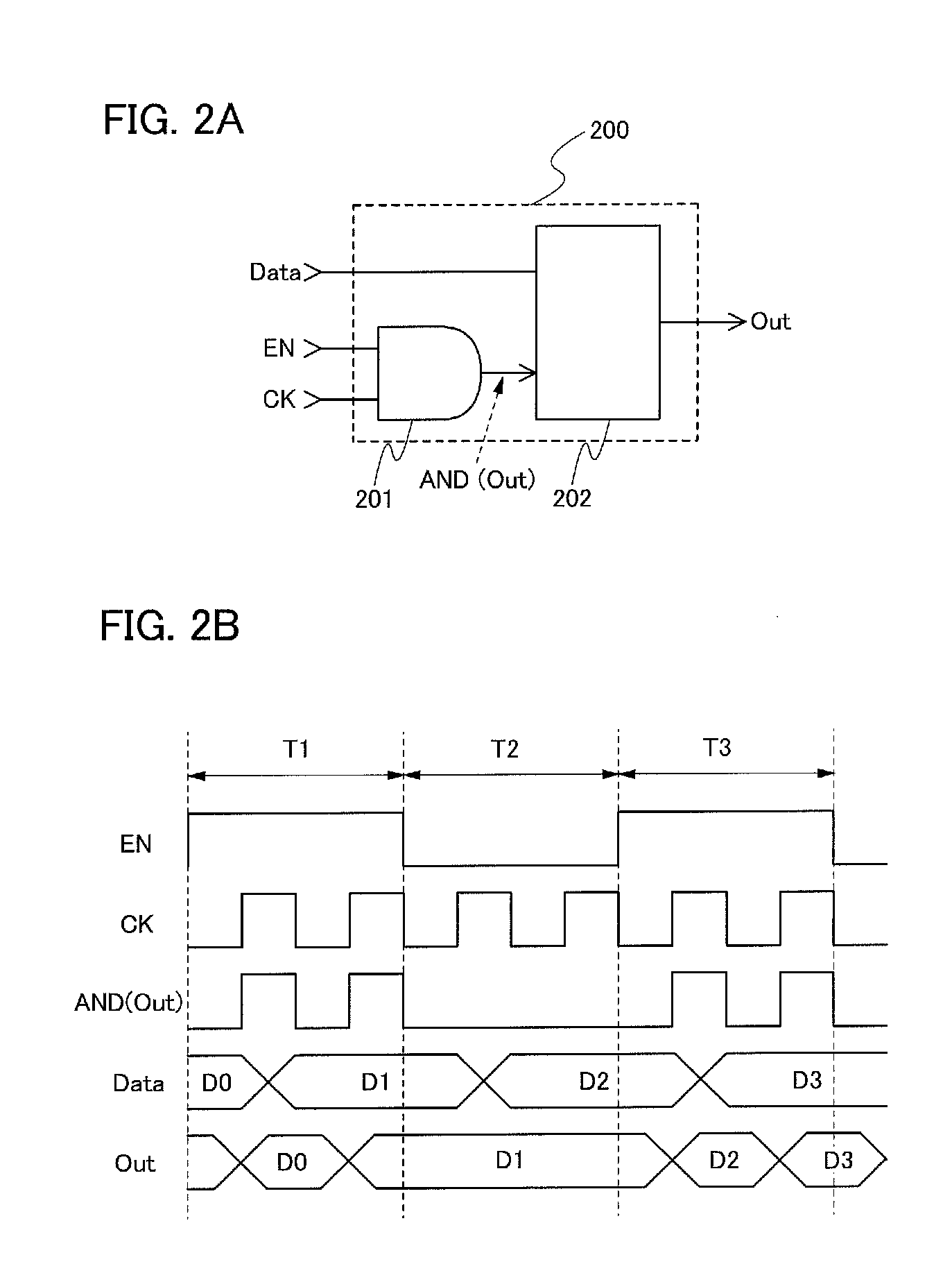
[0055]In this embodiment, an example of the logic circuit described in Embodiment I will be described. Specifically, a logic circuit including an AND gate and a flip-flop will be described with reference to FIGS. 2A and 2B, FIGS. 3A and 3B, and FIGS. 4A to 4C.
[0056]A logic circuit 200 of this embodiment shown in FIG. 2A includes an AND gate 201 and a flip-flop 202. The AND gate 201 has a first input terminal which is electrically connected to a wiring through which an enable signal (EN) is supplied (hereinafter, also referred to as an enable signal line) and a second input terminal which is electrically connected to a wiring through which a clock signal (CK) is supplied (hereinafter, also referred to as a clock signal line). The flip-flop 202 has a first input terminal which is electrically connected to a data signal line and a second input terminal which is electrically connected to an output terminal of the AND gate 201.
[0057]Note that the flip-flop 202 included in the logic circu...
embodiment 3
[0107]In this embodiment, an example of the logic circuit described in Embodiment I will be described. Specifically, a logic circuit including a NOR gate and a flip-flop will be described with reference to FIGS. 5A and 5B and FIGS. 6A and 6B.
[0108]A logic circuit 500 of this embodiment shown in FIG. 5A includes a NOR gate 501 and a flip-flop 502. In the NOR gate 501, a first input terminal is electrically connected to an enable signal line and a second input terminal is electrically connected to a wiring through which an inverted circuit signal (CKB) is supplied (hereinafter, also referred to as an inverted clock signal line). In the flip-flop 502, a first input terminal is electrically connected to a data signal line and a second input terminal is electrically connected to an output terminal of the NOR gate 501.
[0109]Note that the flip-flop 502 included in the logic circuit of this embodiment is a circuit which can retain data for one bit utilizing feedback operation. An output sig...
PUM
 Abstract
Description
Claims
Application Information
 - R&D
- Intellectual Property
- Life Sciences
- Materials
- Tech Scout
- Unparalleled Data Quality
- Higher Quality Content
- 60% Fewer Hallucinations
Browse by: Latest US Patents, China's latest patents, Technical Efficacy Thesaurus, Application Domain, Technology Topic, Popular Technical Reports.
© 2025 PatSnap. All rights reserved.Legal|Privacy policy|Modern Slavery Act Transparency Statement|Sitemap|About US| Contact US: help@patsnap.com


