
Electrode for lead-acid battery and method for producing such an electrode

a lead-acid battery and electrode technology, applied in the field of electrodes for lead-acid batteries, to achieve the effect of improving mechanical and electrical connections

Inactive Publication Date: 2011-04-14
COMMISSARIAT A LENERGIE ATOMIQUE ET AUX ENERGIES ALTERNATIVES
View PDF11 Cites 16 Cited by
  • Summary
  • Abstract
  • Description
  • Claims
  • Application Information

AI Technical Summary

Benefits of technology

[0028]More particularly, one object of the invention is to provide an electrode for lead-acid battery comprising a glassy carbon substrate, an intermediate layer deposited on the glassy carbon substrate and an active layer of a lead-containing paste covering the intermediate layer, having improved mechanical and electrical connection between the lead-containing paste and the substrate and a stabilized interface between the substrate and the intermediate layer even if deep discharge conditions are applied.

Problems solved by technology

However, the main drawback of the lead-acid batteries is their low specific energy.
These low values of the specific energy result from the low utilization efficiency of the active materials in conjunction with the heavy weight of the lead current collectors.
However the deposition process of the lead layer on the surface of aluminium and aluminium alloys is rather expensive and complicated.
Furthermore any unprotected aluminium surface resulted from cracks or fissures of the lead layer will lead to accelerated grid corrosion process, causing fast battery failure.
Since the ABS is an insulator, the current collectors will show much higher electrical resistance and the plastic substrate is also unsuitable in a further cast on strap process also called COS process.
Indeed, the electroplated polyaniline layer used in the article of B. Hariprakash et al. degrades fast under the high potential of the operation of the positive plate.
Moreover, the graphite is a very soft material and its surface cannot withstand the changes mechanical stress during the charge and the discharge and the quality of the lead layer is poor, causing fast peeling.
However, the direct use of carbon foam as current collector for the positive plates is strictly limited due to the anodic degradation of the material in the potential domain of the oxygen evolution and the anodic degradation causes fast capacity loss in the first few cycles
Such current collectors have the following drawbacks:as the surface of the RVC substrate is substantial, forming tab and frame can decrease substantially the specific energy of the battery,the internal resistance of the corresponding battery can be high due to the low ohmic resistance of the reticulated vitreous carbon,the reticulated vitreous carbon is brittle and the performance of the battery can be disappointing during operation under vibrations and other kinds of mechanical stress,the pasting operation with a RVC substrate coated by lead or lead-tin alloy is markedly harder than the pasting operation with other conventional grids,applying compression of the active block is nearly impossible, because the reticulated structure has poor elastic properties.
The absence of compression leads to fast softening and peeling of the positive active material from the supporting grid at deep discharge or high rate cycling and to decrease in capacity.
However, it isn't stable at deep discharge conditions and in the absence of the PbO2 corrosion layer generally formed from a metallic lead support, the positive active material can easy loss the mechanical and electrical connection with the carbon support.

Method used


Image

  • Electrode for lead-acid battery and method for producing such an electrode
  • Electrode for lead-acid battery and method for producing such an electrode
  • Electrode for lead-acid battery and method for producing such an electrode

Examples


Embodiment Construction

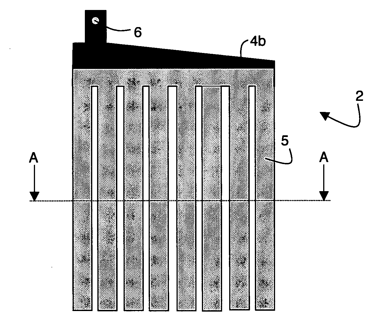
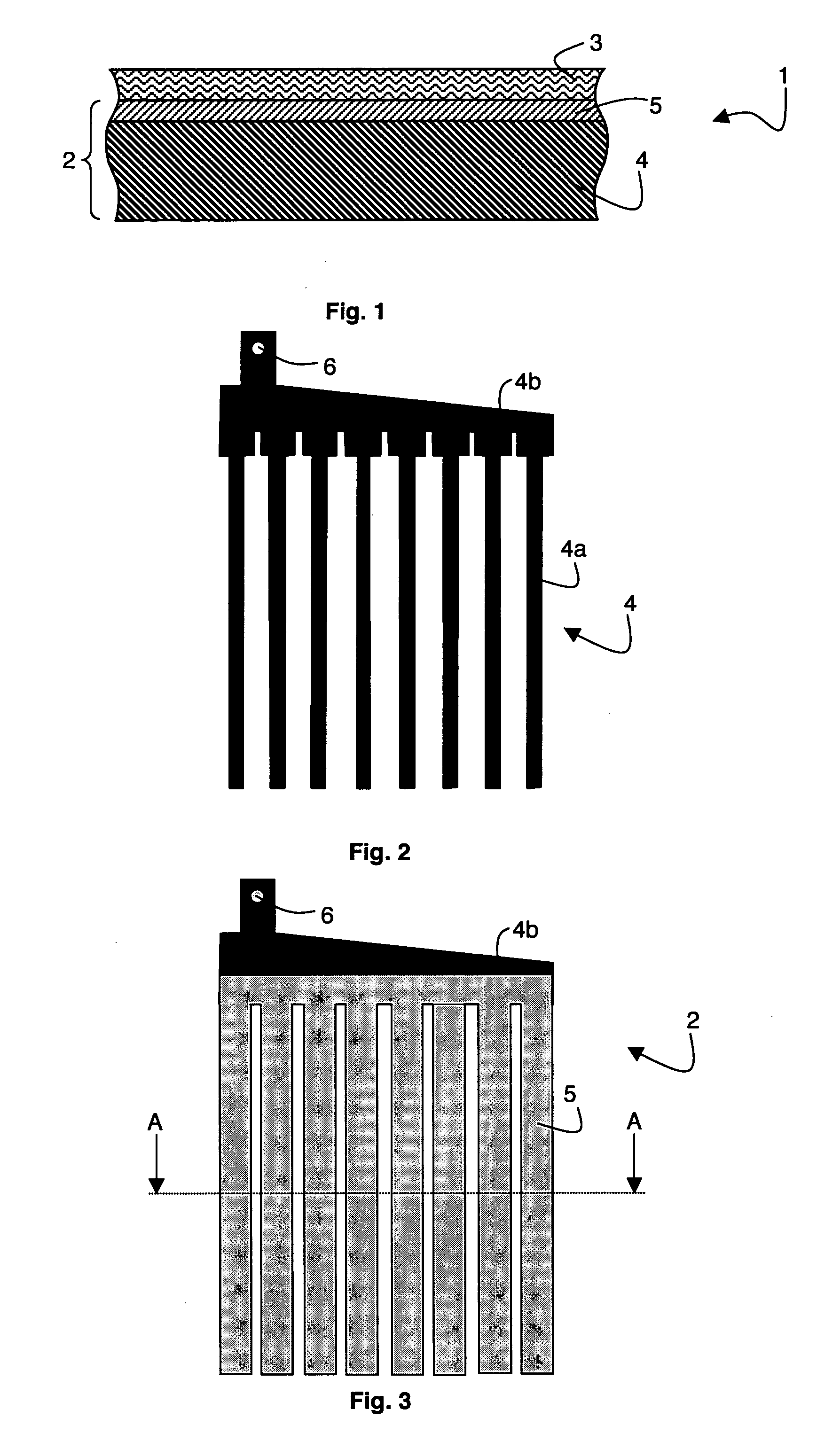
[0038]As represented in FIG. 1, an electrode 1 for lead-battery comprises a current collector 2 covered by an active layer 3 of lead-containing paste. The current collector 2 is formed by a glassy carbon substrate 4 on which is deposited an intermediate layer 5. The glassy carbon substrate 4 has preferably a thickness comprised between 1 mm and 3 mm whereas the thickness of the intermediate layer 5 is advantageously comprised between 50 μm and 200 μm.

[0039]The glassy carbon material is also called vitreous carbon, glassy polymeric carbon or vitreous polymeric carbon. The glassy carbon is a special form of carbon. It is a low-porous carbon. Thus, the glassy carbon substrate 4 comprises pores but the volume of these pores only represent between 0% and 10% of the apparent volume of the substrate. More particularly, the ratio between the volume of pores and the apparent volume is comprised between 1% and 6%. In addition, the glassy carbon material presents high electric conductivity pro...


PUM

PropertyMeasurementUnit
Fractionaaaaaaaaaa
Fractionaaaaaaaaaa
Fractionaaaaaaaaaa

Abstract

An electrode for lead-battery comprises a current collector covered by an active layer of lead-containing paste. The current is formed by a glassy carbon substrate on which is deposited an intermediate layer. The glassy carbon substrate has preferably a thickness comprised between 1 mm and 3 mm whereas the thickness of the intermediate layer is advantageously comprised between 50 μm and 200 μm. In a particular embodiment, the glassy carbon substrate is in form of a comb.

Description

BACKGROUND OF THE INVENTION[0001]The invention relates to an electrode for lead-acid battery comprising :[0002]a glassy carbon substrate[0003]an intermediate layer deposited on the glassy carbon substrate[0004]and an active layer of a lead-containing paste covering the intermediate layer.[0005]The invention also related to a method for producing such an electrode.STATE OF THE ART[0006]Lead-acid battery is known to include at least one positive current collector, at least one negative current collector and an electrolytic solution. Usually, the negative and positive current collectors are lead grids or lead plates of various configurations (flat-plates, tubular-plates . . . ) and on which is disposed an active material paste in order to form an electrode. Storage and release of electrical energy in lead-acid batteries is enabled by chemical reactions that occur in the paste.[0007]However, the main drawback of the lead-acid batteries is their low specific energy. Flat-plate lead-acid ...

Claims


Application Information

Patent Timeline
IPC IPC(8): C25D5/54H01M50/541
CPCC04B35/524H01M4/0433H01M4/0452H01M4/16Y02E60/126H01M4/663H01M4/685H01M4/73H01M10/06H01M4/20Y02E60/10
Inventor KIRCHEV, ANGEL ZHIVKOV
Owner COMMISSARIAT A LENERGIE ATOMIQUE ET AUX ENERGIES ALTERNATIVES
Learn More