
Replaceable upper chamber parts of plasma processing apparatus

a plasma processing apparatus and upper chamber technology, applied in the direction of coatings, chemical vapor deposition coatings, electric discharge tubes, etc., can solve the problems of difficult to correctly reseal unfavorable temperature increase of adjacent components, and difficult reseal of the upper chamber section after maintenan

Active Publication Date: 2011-03-10
LAM RES CORP
View PDF53 Cites 414 Cited by
  • Summary
  • Abstract
  • Description
  • Claims
  • Application Information

AI Technical Summary

Benefits of technology

[0015]In a preferred embodiment, a replaceable top chamber interface of an upper chamber section of a plasma reaction chamber in which semiconductor substrates can be processed, comprises a monolithic metal cylinder having a uniform diameter inner surface, an upper vacuum sealing surface extending horizontally away from the inner surface and a lower vacuum sealing surface extending horizontally away from the inner surface; the upper annular vacuum sealing surface adapted to seal against a dielectric window of the plasma chamber; the lower annular vacuum sealing surface adapted to seal against a bottom section of the plasma chamber; a thermal mass at an upper portion of the cylinder, the thermal mass defined by a wider portion of the cylinder between the inner surface and an outer surface extending vertically from the upper flange, the thermal mass being effective to provide azimuthal temperature uniformity of the inner surface, and a thermal choke at a lower portion of the cylinder effective to minimize transfer of heat across the lower vacuum sealing surface, the thermal choke defined by a thin metal section having a thickness of less than 0.25 inch and extending at least 25% of the length of the inner surface.

Problems solved by technology

Cleaning is problematic in that the ceramic coatings of this type are easily damaged and due to the sensitive processing of some plasma processes, it is sometimes preferred to replace the upper chamber section rather than remove it for cleaning.
In addition, correctly reseating the upper chamber section after maintenance is often difficult, since it must properly be aligned with the bottom chamber section such that a set of gaskets properly seal around the upper chamber section.
However, plasma processing may require temperature changes during multi-step processing and it may be necessary to heat the upper chamber section to temperatures above 100° C., e.g. 120, 130, 140, 150 or 160° C. or any temperature therebetween whereas the prior upper chamber sections were run at much lower temperatures on the order of 60° C. The higher temperatures can cause undesirable increases in temperature of adjacent components such as the bottom chamber section.
Thus, heat flow variations originating from the upper chamber section may cause the substrate temperature to vary outside narrow recipe parameters.

Method used


Image

  • Replaceable upper chamber parts of plasma processing apparatus
  • Replaceable upper chamber parts of plasma processing apparatus
  • Replaceable upper chamber parts of plasma processing apparatus

Examples


Embodiment Construction

[0024]The present invention will now be described in detail with reference to a few preferred embodiments thereof as illustrated in the accompanying drawings. In the following description, numerous specific details are set forth in order to provide a thorough understanding of the present invention. It will be apparent, however, to one skilled in the art, that the present invention may be practiced without some or all of these specific details. In other instances, well known process steps and / or structures have not been described in detail in order to not unnecessarily obscure the present invention. As used herein, the term “about” should be construed to include values up to 10% above or below the values recited.

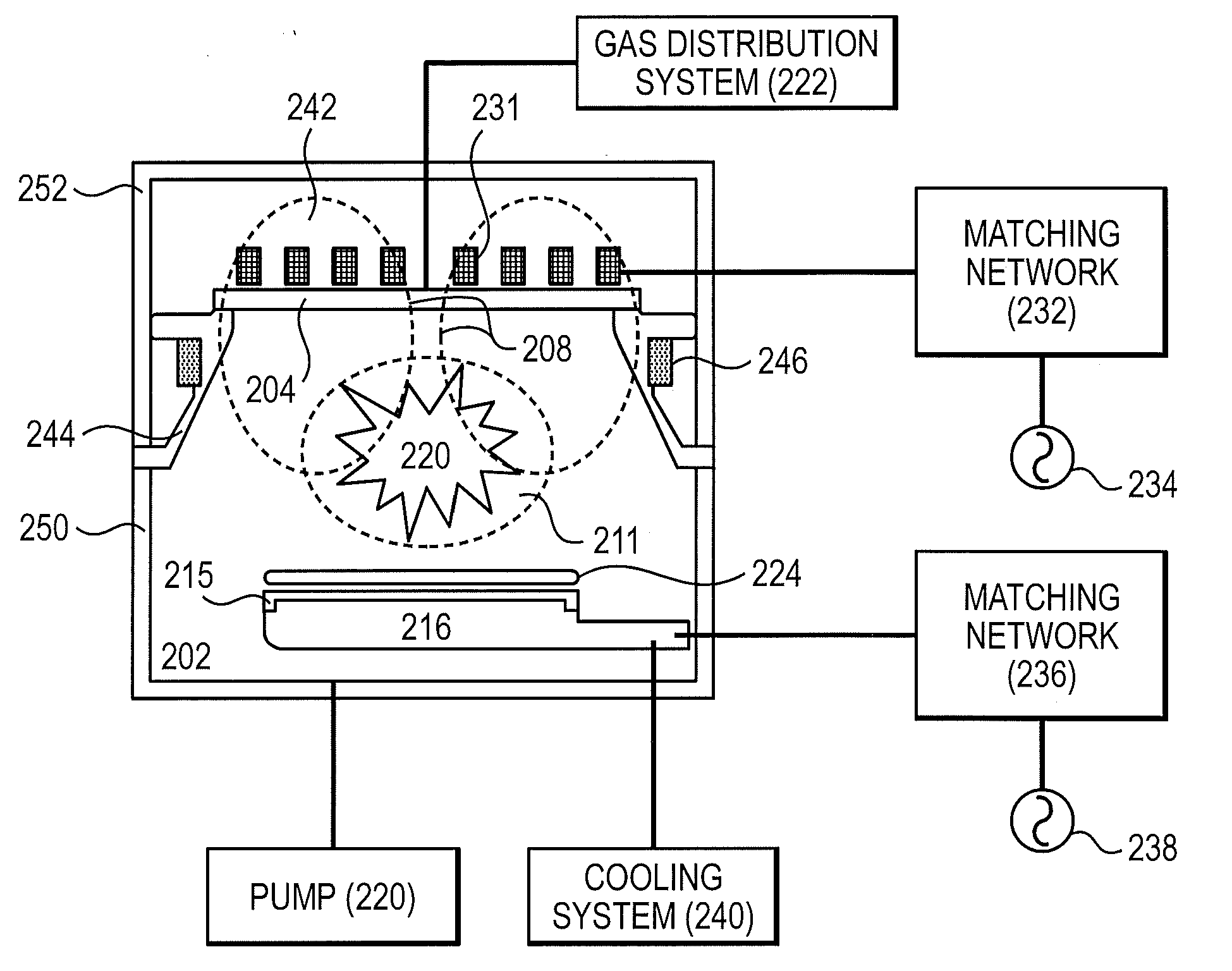
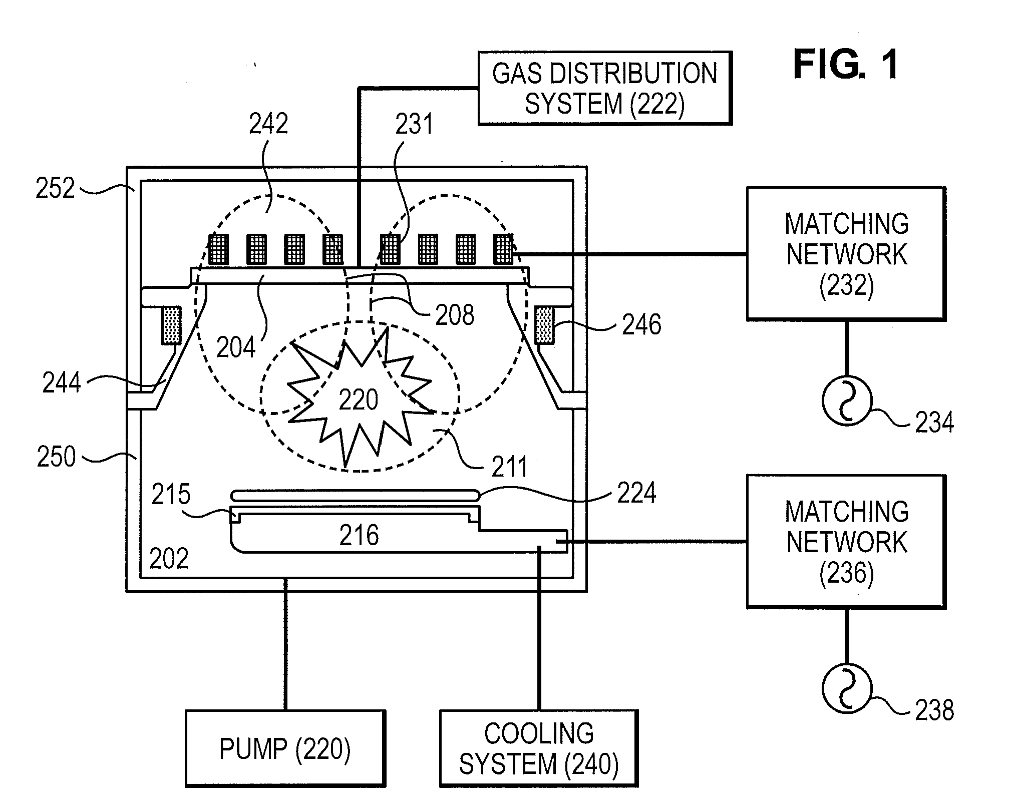
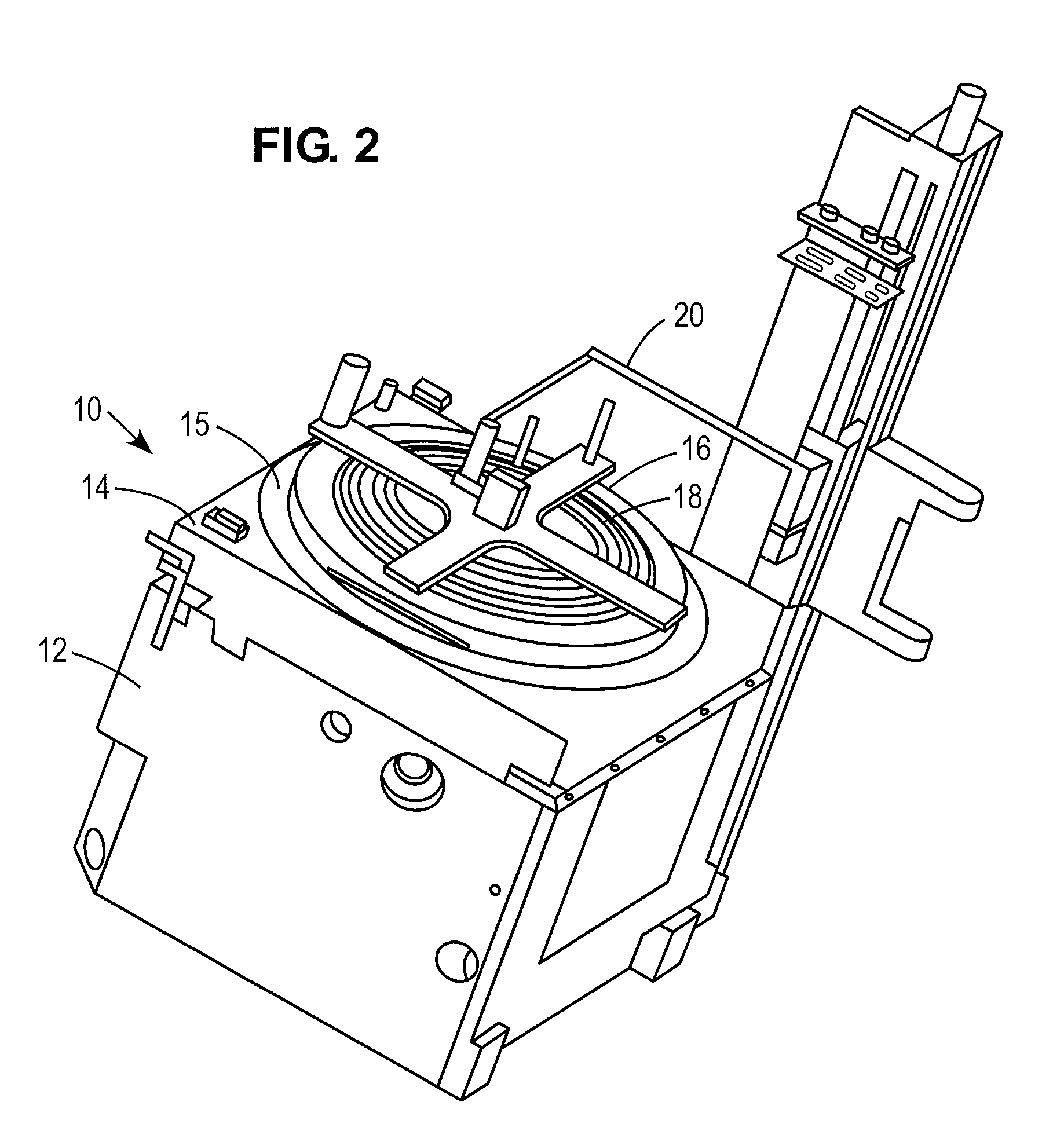
[0025]Described herein are replaceable parts of an upper chamber section of a plasma chamber such as that illustrated in FIG. 2. The parts include a ceramic window, top chamber interface and side gas injection delivery system.

[0026]The plasma system shown in FIG. 2 includes a...


PUM

PropertyMeasurementUnit
Lengthaaaaaaaaaa
Lengthaaaaaaaaaa
Lengthaaaaaaaaaa

Abstract

An upper chamber section of a plasma reaction chamber includes a ceramic window with blind bores in an upper surface for receipt of a thermal couple and a resistance temperature detector, a top chamber interface which comprises an upper surface which vacuum seals against the bottom of the window and a gas injection system comprising 8 side injectors mounted in the sidewall of the top chamber interface and a gas delivery system comprising tubing which provides symmetric gas flow to the 8 injectors from a single gas feed connection.

Description

[0001]This application claims priority under 35 U.S.C. §119 to U.S. provisional application No. 61 / 241,321 entitled REPLACEABLE UPPER CHAMBER PARTS OF PLASMA PROCESSING APPARATUS, filed Sep. 10, 2009, the entire content of which is hereby incorporated by reference.FIELD OF THE INVENTION[0002]The present invention relates in general to semiconductor substrate manufacturing technologies and in particular to a replacement parts of an upper chamber section of a plasma chamber.BACKGROUND OF THE INVENTION[0003]In the processing of a substrate, e.g., a semiconductor substrate or a glass panel such as one used in flat panel display manufacturing, plasma is often employed. As part of the processing of a substrate for example, the substrate is divided into a plurality of dies, or rectangular areas, each of which will become an integrated circuit. The substrate is then processed in a series of steps in which materials are selectively removed (etching) and deposited (deposition) in order to for...

Claims


Application Information

Patent Timeline
IPC IPC(8): H01L21/306
CPCH01J37/321H01J37/32449H01J37/32458H01J37/32522H01J37/32119H01J37/32513H01J37/3244H01J37/32477H01J37/32495H01L21/67248C23C16/45563C23C16/45578
Inventor BROWN, DANIEL ARTHURBOGART, JEFF A.KENWORTHY, IAN J.
Owner LAM RES CORP
Learn More