
Recording apparatus equipped with heatsink

a recording apparatus and heatsink technology, applied in the field of recording apparatuses, can solve the problems of increasing the heat generated by the driver element, the noise of the signal fed through the wire, and the change in the actuation property of the actuator, so as to prevent the heat transfer

Active Publication Date: 2007-03-13
BROTHER KOGYO KK
View PDF21 Cites 24 Cited by
  • Summary
  • Abstract
  • Description
  • Claims
  • Application Information

AI Technical Summary

Benefits of technology

[0008]The present invention was made in view of the background prior art discussed above. It is therefore an object of the present invention to provide a recording apparatus capable of preventing deterioration in the quality of the printed image, which could be caused if the head unit of the apparatus were thermally affected. This object may be achieved according to any one of first through fifth aspects of the invention which are described below.
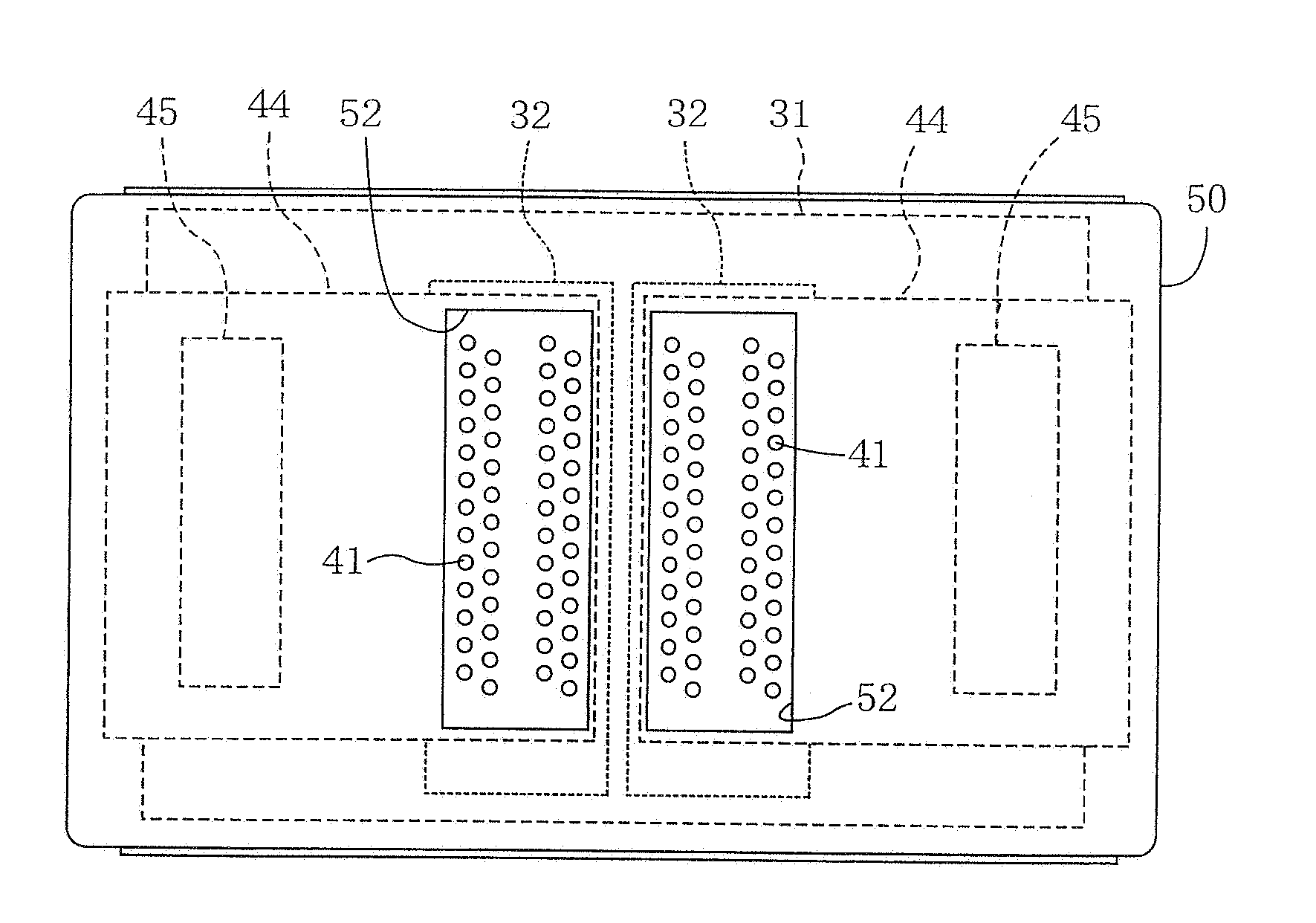
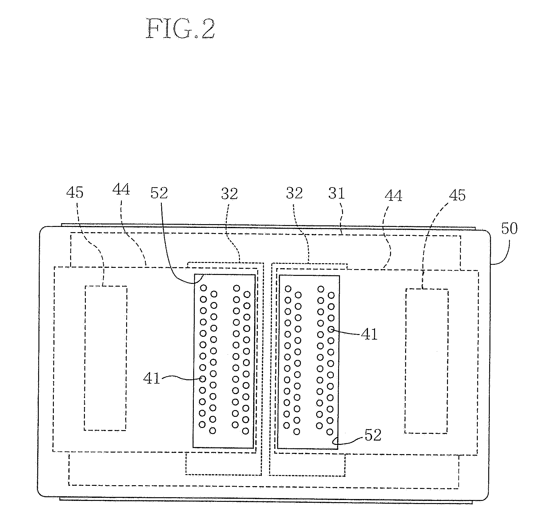
[0010]In the present recording apparatus, the heatsink is disposed in thermally conductive communication with the driver element, so as to radiate or dissipate heat generated by activation of the driver element. When the driver element is activated at a high processing speed, an amount of the generated heat is increased whereby the heatsink is also heated to have a high temperature. However, owing to the void portion of the heatsink which portion is opposed to the heat unit, it is possible to minimize transfer of the heat from the heatsink to the head unit, even if the driver element is positioned to be close to the head unit. Thus, the head unit is prevented from being considerably heated or thermally affected, whereby deterioration in the quality of the printed image can be minimized.
[0012]In the recording apparatus according to the second aspect of the invention in which the head unit includes the cavity unit and the piezoelectric actuator are superposed on each other, considerable changes in the actuation property of the piezoelectric elements and the physical property of the ink are prevented even if the heatsink is heated to have a high temperature. That is, it is possible to provide an ink-jet head capable of preventing deterioration in the quality of the printed image, which could be caused if the head unit were thermally affected by the heatsink.
[0016]In the recording apparatus according to the fourth aspect of the invention, the head unit is prevented from being considerably heated by the heat transferred from the heatsink, owing to the plurality of holes of the void portion of the heatsink which is opposed to the head unit. Since the void portion includes the plurality of through-holes, it is possible to design number, sizes and positions of the through-holes with a high degree of freedom. Thus, the void portion has a high degree of freedom of design in its arrangement.
[0018]In the recording apparatus according to the fifth aspect of the invention, the heat dissipation member, which is independent from the heatsink having the void portion, is disposed in thermally conductive communication with the head unit. The heat dissipation member serves to remove the heat generated by the head unit per se, for thereby preventing the head unit from being considerably heated by the heat generated by itself. Further, since the heat dissipation member is disposed without its contact with the heatsink, it is possible to prevent transfer of the heat from the heatsink to the heat dissipation member.

Problems solved by technology

Due to the denser wiring arrangement and the finer wire, signals fed through the wires tend to be easily affected by noises.
However, the increased number of nozzles leads to an increase in amount of heat generated by the driver element, and the increased amount of heat is easily transferred through the body frame or the heatsink, to the actuator which is positioned to be close to the driver element.
With the actuator being heated by the heat, the actuator suffers from change in its actuation property (particularly, where piezoelectric elements are used in the actuator).
The changes in the actuation property of the actuator and the physical property of the ink cause deterioration in the quality of the printed image.

Method used


Image

  • Recording apparatus equipped with heatsink
  • Recording apparatus equipped with heatsink
  • Recording apparatus equipped with heatsink

Examples


Embodiment Construction

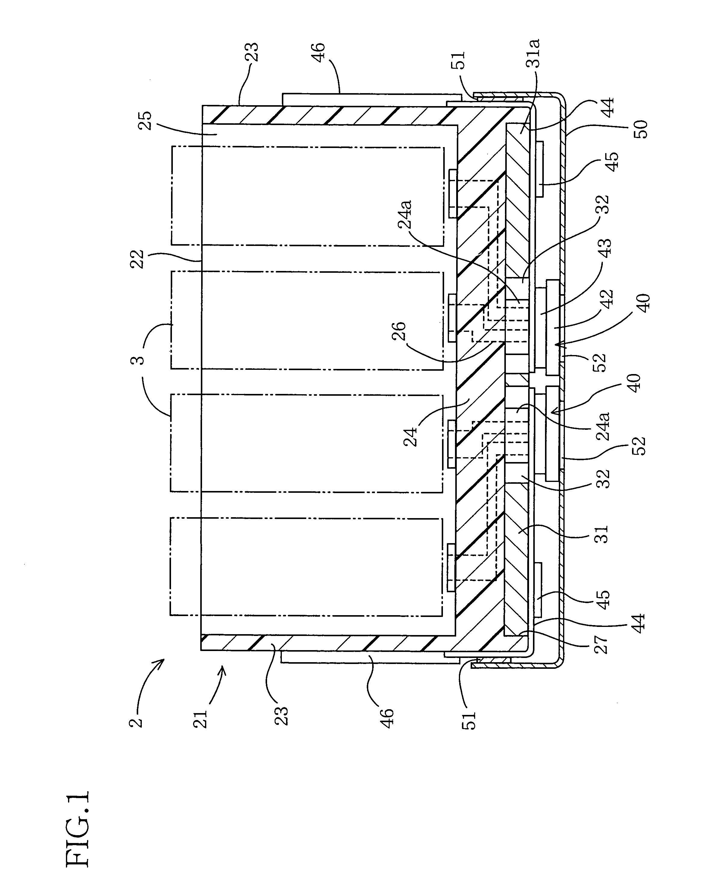
[0027]FIG. 1 shows a recording head portion 2 provided in a recording apparatus constructed according to an embodiment of the invention. As in a common recording apparatus, this recording head portion 2 is mounted on a carriage (not shown) which is arranged to be movable along a recording medium, so that ink droplets are ejected from head units provided in the recording head portion 2, for recording desired patterns of images on the recording medium.

[0028]The recording head portion 2 has a body frame 21 which is formed of a synthetic resin such as polyethylene and polypropylene by an injection molding machine. The body frame 21 is provided by a box-like structure, and has an upper open end. Described more specifically, the body frame 21 has a bottom plate 24, a pair of side plates 23 respectively extending upwardly from right and left ends of the bottom plate 24, and a back plate 22 extending upwardly from a rear end portion of the bottom plate 24. The body frame 21 has, in its insi...


PUM


Abstract

A recording apparatus having: (a) a head unit including an actuator which generates energy required for recording predetermined patterns of image on a recording medium; (b) a circuit board including a driver element which drives the actuator of the head unit; and (c) a heatsink disposed in thermally conductive communication with the driver element. The heatsink has a void portion which is opposed to the head unit.

Description

[0001]This application is based on Japanese Patent Application No. 2003-085663 filed in Mar. 26, 2003, the content of which is incorporated hereinto by reference.BACKGROUND OF THE INVENTION[0002]1. Field of the Invention[0003]The present invention relates in general to a recording apparatus equipped with (a) a head unit including an actuator which generates energy required for recording predetermined patterns of image on a recording medium, (b) a circuit board including a driver element which drives the actuator, and (c) a heatsink disposed in thermally conductive communication with the driver element.[0004]2. Discussion of Related Art[0005]There is known a recording apparatus equipped with (a) a head unit including an actuator which generates energy required for recording predetermined patterns of image on a recording medium, (b) a circuit board including a driver element which drives the actuator, and (c) a heatsink disposed in thermally conductive communication with the driver el...

Claims


Application Information

Patent Timeline
IPC IPC(8): B41J29/377B41J2/01B41J2/045B41J2/055B41J2/14
CPCB41J29/377B41J2/1408
Inventor KUBO, TOMOYUKI
Owner BROTHER KOGYO KK
Learn More