Method of forming a trench isolation

Inactive Publication Date: 2011-03-03
JSR CORPORATIOON
View PDF6 Cites 3 Cited by
  • Summary
  • Abstract
  • Description
  • Claims
  • Application Information

AI Technical Summary

Benefits of technology

[0010]According to the present invention, the above object and advantage of the present invention are attained by a method of forming a trench isolation, comprising the steps of:

Problems solved by technology

However, in the trench isolation formed by the above method, even if an insulator made of silicon dioxide is formed in each trench by chemical vapor deposition having relatively high coverage, when the aspect ratio (trench depth / trench width) of the trench becomes not less than 1, a local void is formed in the inside of the formed silicon dioxide.
Therefore, when a heat treatment step is carried out after that, the formed void may expand and destroy the trench isolation.
However, even in this method, a local void is formed in the silicon dioxide deposition layer formed in the inside of a trench having an aspect ratio of not less than 2.
Since the silicon dioxide deposition layer formed by this chemical vapor deposition process has a lower density than that of a silicon dioxide deposition layer formed by another chemical vapor deposition process, it is difficult to form a silicon dioxide insulator having high resistance.
Further, an expensive vacuum apparatus is required in all the above methods, thereby boosting costs.
In addition, since the raw material is gaseous, the methods have problems to be solved, such as the contamination of the apparatus and low production yield due to the generation of foreign matter.
However, when the aspect ratio of a trench formed in the substrate is large, it is difficult to fill the trench with a coating type composition containing the super high molecular weight substance by coating, whereby a local void is readily formed as well.

Method used


Image

  • Method of forming a trench isolation
  • Method of forming a trench isolation
  • Method of forming a trench isolation

Examples


synthesis example 1

Synthesis Example of Silicon Compound Represented by the Above Formula (2)

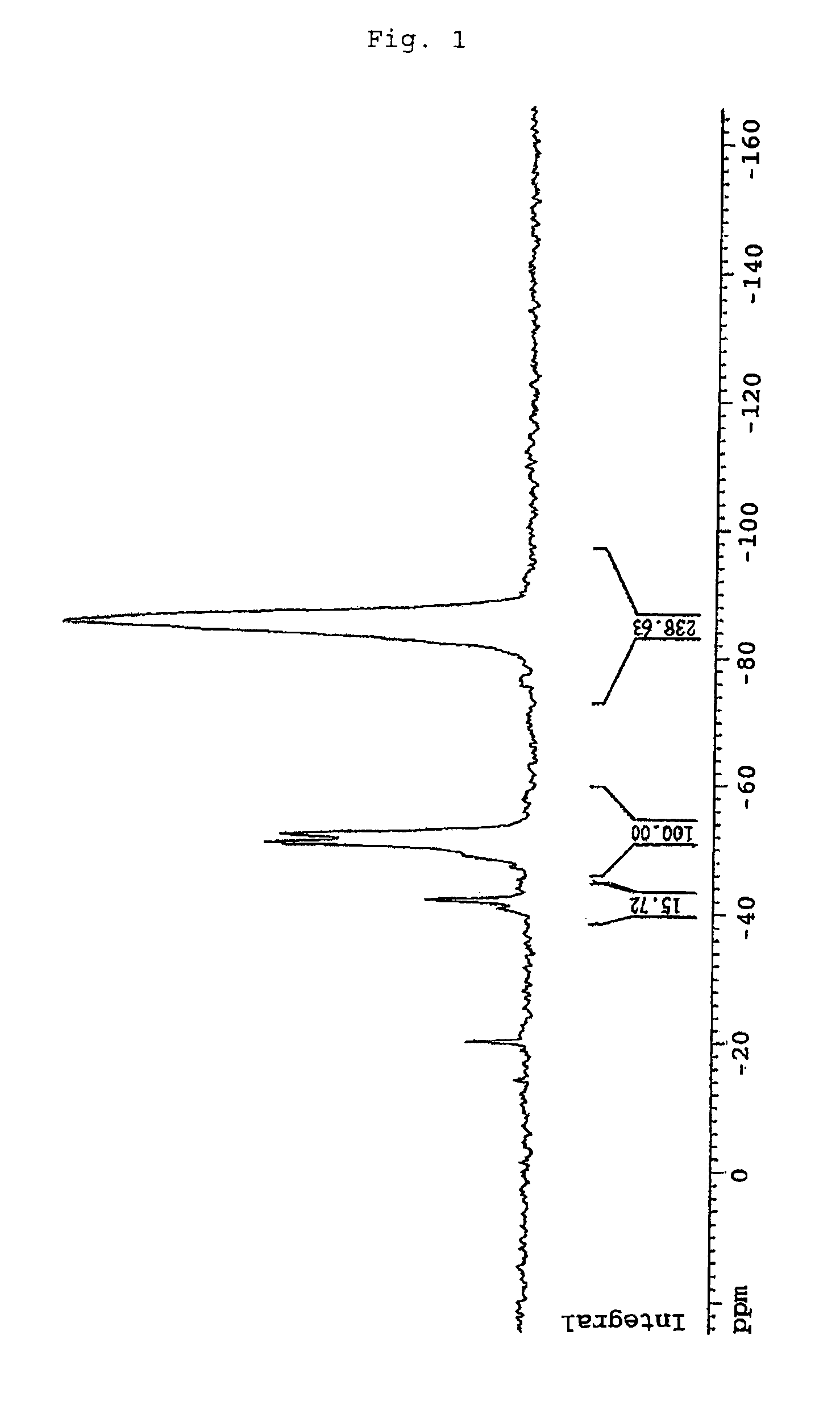
[0095]A Dewer condenser, an air introduction tube, a thermometer and a septum were set in a 1-L four-necked flask, and 400 mL of n-butyl ether was fed to the flask in a nitrogen atmosphere. After this reaction system was cooled to −20° C. in a cooling bath, liquefied H2SiCl2 (84 g, 820 mmol) was injected into the flask by a syringe. Distilled water (14.8 mL, 820 mmol) was added dropwise at the same temperature (−20° C.) over 60 minutes and then stirred for 1 hour. Thereafter, the reaction liquid was transferred to a separatory funnel and washed with 400 mL of distilled water 4 times, and an n-butyl ether layer was dried with magnesium sulfate and filtered to obtain a solution containing a silicon compound (2-1). When this solution containing the silicon compound (2-1) was measured by 1H-NMR and 29Si-NMR, a plurality of peaks derived from Si—H2 were seen at 4.8 to 4.6 ppm in the 1H-NMR measurement and other pea...

synthesis example 2

Synthesis Example of Silicone Resin Represented by the Above Rational Formula (1)

[0098]125 g of the distillate containing the silicon compound (2-1) (containing 4.8 wt % of the silicon compound (2-1)) obtained in the above Synthesis Example 1, n-butyl ether (33 g) and propylene glycol monoethyl ether acetate (20 g) were added to a 300 mL three-necked flask equipped with a thermometer and a dropping funnel in the air and stirred at 0° C., and 1.32 mL of a solution prepared by dissolving triethylamine in n-butyl ether to a concentration of 0.1 wt %, distilled water (0.82 g, 45 mmol) and propylene glycol monoethyl ether acetate (20 g) were added dropwise over 10 minutes and then stirred for 2 hours.

[0099]Thereafter, 1.76 g of an n-butyl ether solution containing 0.1 wt % of oxalic acid was added to the reaction liquid to terminate the reaction. The reaction liquid was transferred to a separatory funnel and washed with distilled water 4 times, an organic layer was dried with MgSO4 and f...

synthesis example 3

[0105]350 mL of n-hexane, 40 mL of methanol, 20 mL of concentrated sulfuric acid and 48.6 g (0.3 mol) of anhydrous ferric chloride were fed to a 1,000-mL three-necked flask equipped with a dropping funnel in nitrogen, and a solution prepared by dissolving 25 g (0.185 mol) of trichlorosilane in 200 mL of n-hexane was added dropwise to the above mixture under cooling with ice over 10 hours. After the end of addition, they were further stirred at room temperature for 2 hours, the reaction liquid was transferred to a separatory funnel, n-butyl ether was added, an organic layer was washed with 100 mL of distilled water 5 times, dried with calcium chloride and potassium carbonate and filtered and removed the solvent, and further solvent substitution work by vacuum distillation was carried out with n-butyl ether three times to obtain 90 g of a homogeneous transparent n-butyl ether solution containing the silicone resin (1-2).

[0106]This solution containing the silicone resin (1-2) was measu...


PUM

PropertyMeasurementUnit
Temperatureaaaaaaaaaa
Fractionaaaaaaaaaa
Pressureaaaaaaaaaa

Abstract

A method of forming a trench isolation, comprising the steps of:applying a silicone resin composition comprising a silicone resin which is represented by the following rational formula (1) and is solid at 120° C.:(H2SiO)n(HSiO1.5)m(SiO2)k  (1)(wherein n, m and k are each a number, with the proviso that when n+m+k=1, n is 0 to 0.8, m is 0 to 1.0, and k is 0 to 0.2)and an organic solvent to a substrate having trenches in such a manner that the trenches of the substrate are filled with the silicone resin composition so as to form a coating film; andcarrying out the step of bringing the coating film into contact with at least one selected from the group consisting of water, an alcohol and hydrogen peroxide and the step of subjecting the coating film to at least one treatment selected from the group consisting of a heat treatment and an optical treatment.

Description

TECHNICAL FIELD[0001]The present invention relates to a method of forming a trench isolation.BACKGROUND ART[0002]“Trench isolation” is known as a technique for separating from one another the devices of semiconductor equipment formed by integrating a large number of devices at a high density. The trench isolation structure is mainly constructed by forming trenches in a silicon substrate by dry etching, filling the trenches with SiO2 and planarizing a surface over the trenches by chemical mechanical polishing (CMP) in the end. This trench isolation has no increase in isolation size caused by a process such as the bird's beak process as compared with an isolation formed by LOCOS (Local Oxidation of Silicon). Therefore, it is suitable for the high integration of devices.[0003]The above trench isolation structure is generally constructed by, for example, the method described in “First Semiconductor Process” (written by Kazuo Maeda, Kogyo Chosakai Publishing Co., Ltd., pp. 166-173, 2001)...

Claims


Application Information

Patent Timeline
IPC IPC(8): H01L21/762
CPCC08G77/12C08G77/80C08L2203/20C09D183/04H01L21/76224H01L21/02205H01L21/02282H01L21/312H01L21/316H01L21/02164H01L21/02126H01L21/02216
Inventor HATTORI, SEITAROUSEKIGUCHI, MANABUKOKUBO, TERUKAZUTAMAKI, KENTAROFURUKAWA, TSUYOSHIMATSUMOTO, TAICHIMIYAMOTO, CHIAKI
Owner JSR CORPORATIOON
Why Eureka
Try Eureka