
LED lamp with air-cooled heat sink

a heat sink and led lamp technology, applied in the field of head mounted lamps and lights, can solve the problems of not providing adequate light, battery-powered head lamps still pose many limitations, and the cable can become tangled in and/or knocked over medical equipment, etc., and achieve the effect of prolonging the life of leds

Inactive Publication Date: 2011-01-20
MEDINIS DAVID M
View PDF9 Cites 26 Cited by
  • Summary
  • Abstract
  • Description
  • Claims
  • Application Information

AI Technical Summary

Benefits of technology

[0007]The primary object of the present invention is to provide a LED lamp with an air-cooled heat sink that prolongs the life of the LEDs.
[0008]Another object of the present invention is to provide a LED lamp with an air-cooled heat sink that makes the LED lamp safe to wear.
[0009]An even further object of the present invention is to provide a LED lamp with an air-cooled heat sink that makes the LED lamp comfortable for a user to wear.
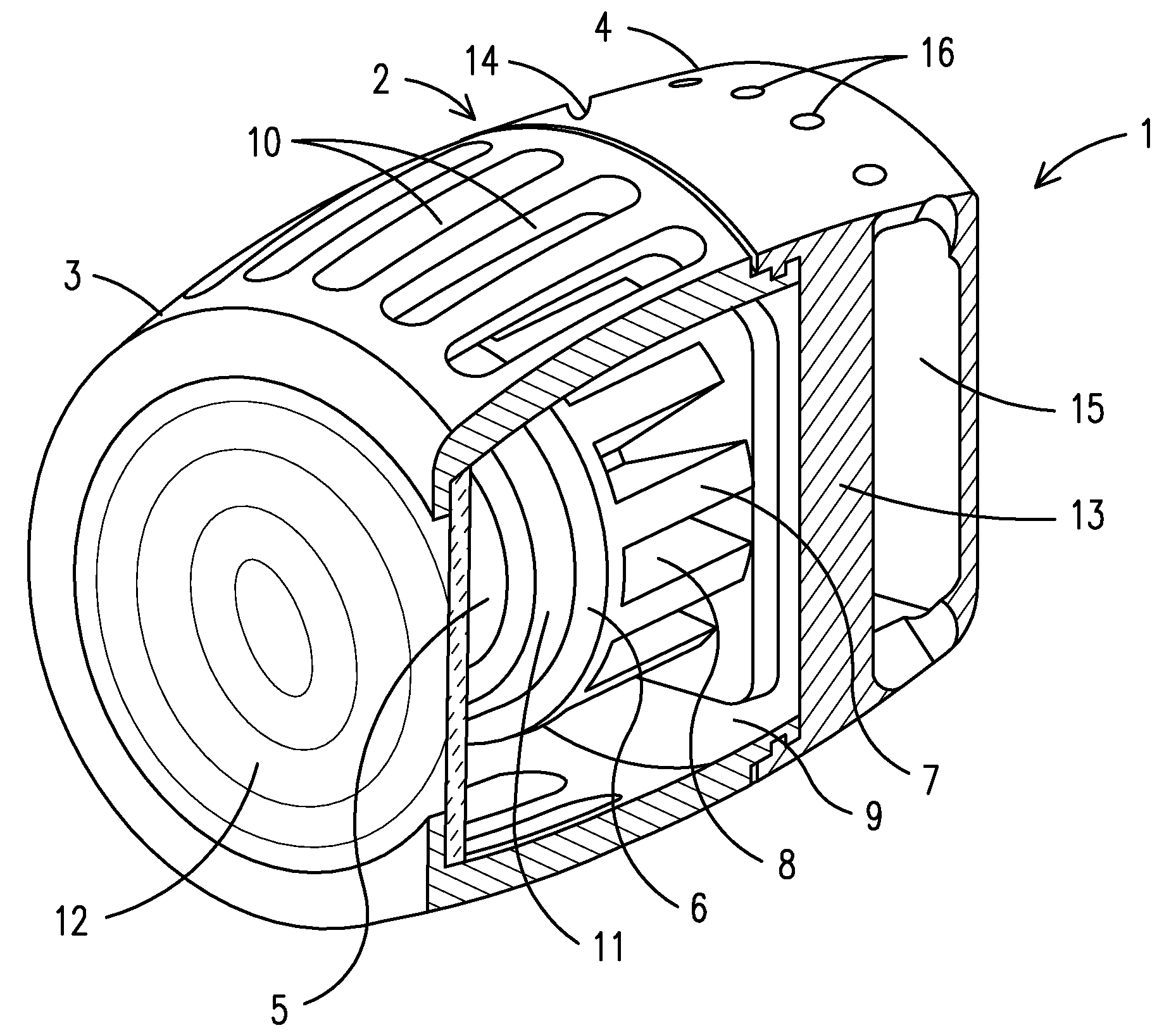
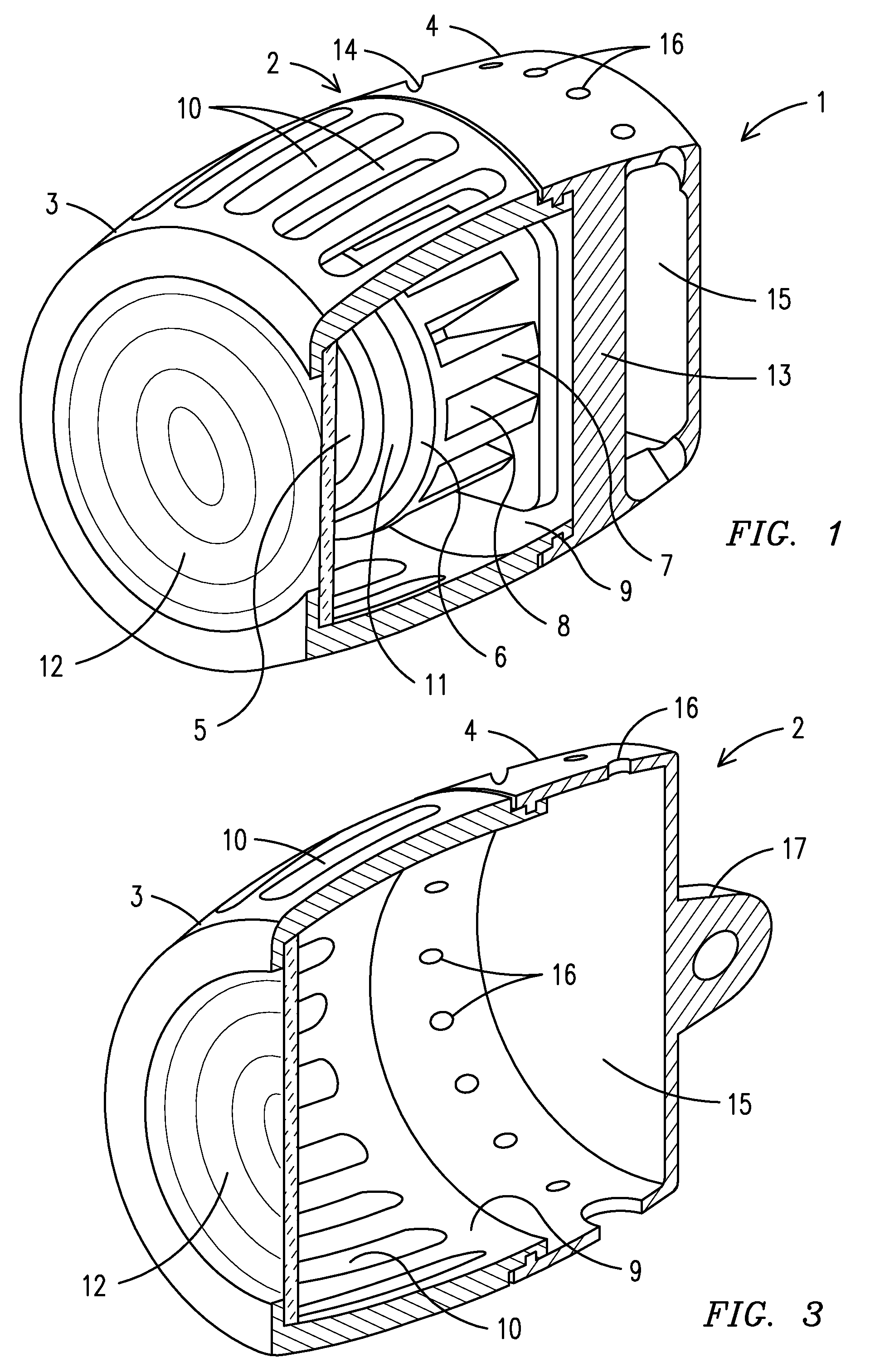
[0010]The present invention fulfills the above and other objects by providing a LED lamp with an air-cooled heat sink comprising a housing having a front section and a rear section that holds at least one LED connected to a heat sink having a plurality of cooling vanes extending therefrom. Heat from the at least one LED travels through the heat sink and then through the cooling vanes. The cooling vanes create additional surface area for air to come into contact with, thereby allowing more efficient cooling of the at least one LED. Cooling channels located between the cooling vanes allow for air flow between the cooling vanes. A cooling chamber that surrounds the heat sink and the cooling vanes allows for air flow around the heat sink and the cooling vanes. A plurality of air inlets located on the surface of the front section of the housing allow for air flow into the front section and cooling chamber. A fan located in the rear housing pulls air through the air inlets into the cooling chamber across the cooling vanes through an exhaust outlet where the fan blows the air into an exhaust chamber located inside the rear housing and finally through exhaust vents located on the rear housing. Further, the cooling vanes are angled so that a venturi effect is created, thereby increasing the airflow across the cooling vanes.
[0011]A reflector mounted behind the at least one LED intensifies the light emitted by the at least one LED. A frenzel lens mounted in front of the at least one LED allows a user to focus the light emitted by the at least one LED. The front section of the housing is moveably attached to the rear section so that a user may rotate the front section clockwise and counterclockwise, thereby focusing or unfocusing the light emitted by the at least one LED through the frenzel lens.

Problems solved by technology

This poses a problem, because the cable limits the user's movement.
In addition there is a possibility that the cable can become tangled in and / or knock over medical equipment.
However, battery powered head lamps still pose many limitations mainly due to the heat generated by the light source.
However, Xenon bulbs do not provide adequate light and xenon bulbs use too much energy, thereby draining the batteries too quickly.
However, LEDs generate an excessive amount of heat that can shorten the life of the LEDs, cause discomfort to the user and / or injure the user.
Such LEDs typically generate so much heat that a heat sink is required to cool the lamps.
A problem with current heat sinks is that they are passively cooled, which does not provide enough heat dissipation.
Alternatively, LEDs may be liquid cooled but liquid cooling still does not provide an adequate amount of heat dissipation.

Method used


Image

  • LED lamp with air-cooled heat sink
  • LED lamp with air-cooled heat sink
  • LED lamp with air-cooled heat sink

Examples


Embodiment Construction

[0020]For purposes of describing the preferred embodiment, the terminology used in reference to the numbered accessories in the drawings is as follows:

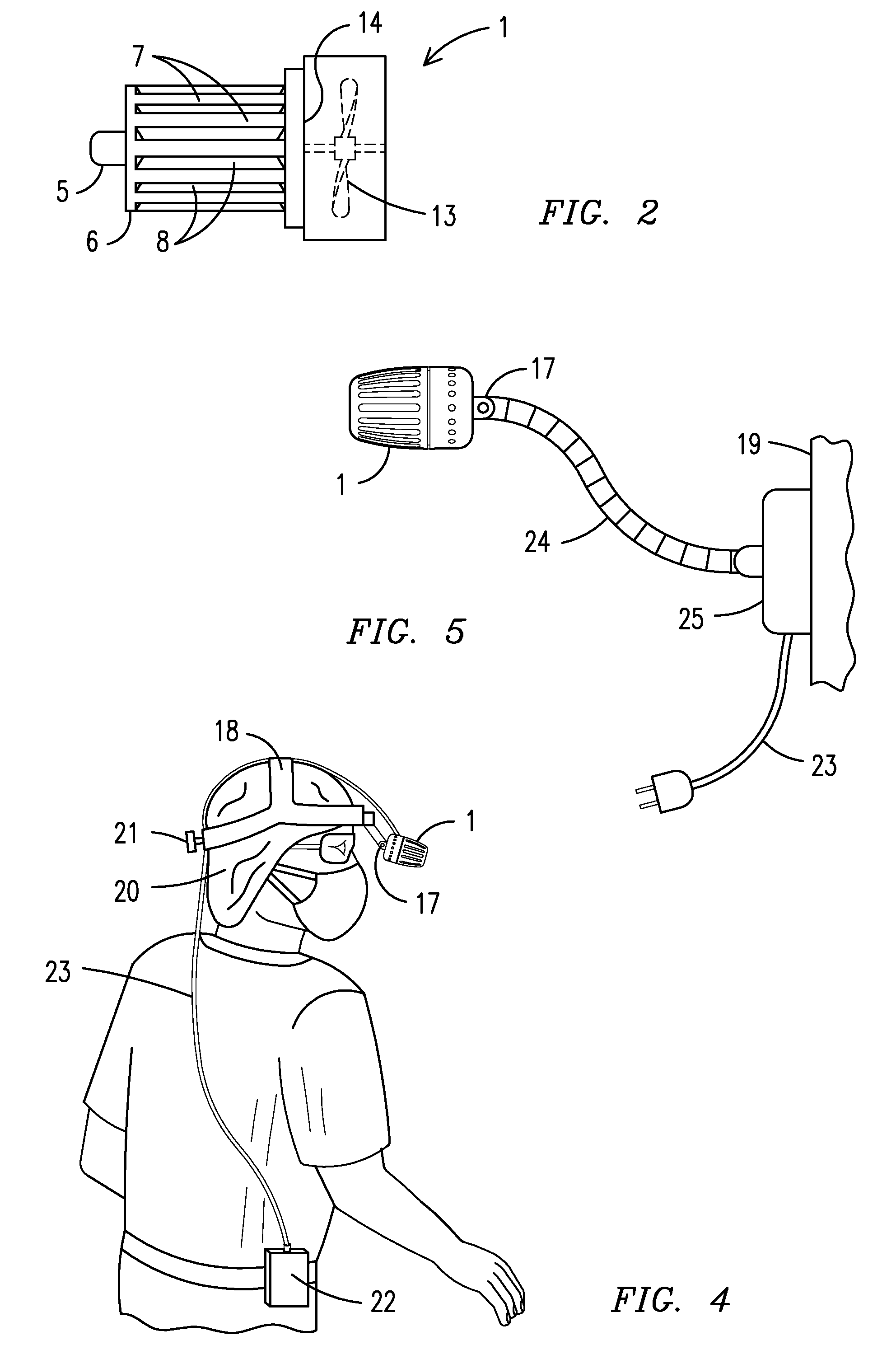
1.LED lamp2.housing3.front section4.rear section5.light emitting diode (“LED”)6.heat sink7.cooling vane8.cooling channels9.cooling chamber10.air inlets11.reflector12.frenzel lens13.fan14.exhaust outlet15.exhaust chamber16.exhaust vents17.bracket18.head strap19.work area20.head21.adjustment means22.battery pack23.power cord24.arm25.mounting bracket

[0021]With reference to FIG. 1, a side perspective partial cutaway view of a LED lamp 1 with an air-cooled heat sink 6 of the present invention is shown. A housing 2 having a front section 3 and a rear section 4 holds at least one light emitting diode LED 5 connected to a heat sink 6 having a plurality of cooling vanes 7 extending therefrom. Heat created by the at least one LED 5 travels through the heat sink 6 and then through the cooling vanes 7. Cooling channels 8 located between the cooli...


PUM


Abstract

A LED lamp (1) having an air-cooled heat sink (6) enclosed in a a housing (2) having a front section (3) and a rear section (4) that holds at least one LED (5) connected to the heat sink. A plurality of cooling vanes (7) extend from the heat sink and heat generated by the at least one LED travels through the heat sink and then through the cooling vanes. The cooling vanes create additional surface area for air to come into contact with, thereby allowing more efficient cooling of the at least one LED. Cooling channels (8) located between the cooling vanes allow for air flow between the cooling vanes. Further, the cooling vanes are angled so that a venturi effect is created as a fan (13) pulls air through the cooling channels, thereby increasing the airflow across the cooling vanes.

Description

CROSS REFERENCE TO RELATED APPLICATION[0001]This application claims the benefit of U.S. Provisional Application No. 60 / 082,350 filed on Jul. 21, 2008.BACKGROUND OF THE INVENTION[0002]This invention relates to head mounted lamps and lights, more particularly, a head mounted light used by surgeons, dentists or other medical personnel or craftsman to illuminate a workspace and allowing the user to have both hands free to perform his or her work.[0003]Currently, head lamps are widely used by surgeons and other medical personnel while performing medical procedures. Head lamps allow surgeons to work freely with both hands while ensuring that the surgeon's work area is adequately illuminated. Many medical personnel use head lamp that are attached to a freestanding light source, and / or to a power outlet or an energy source via fiber optic cable. This poses a problem, because the cable limits the user's movement. In addition there is a possibility that the cable can become tangled in and / or ...

Claims


Application Information

Patent Timeline
IPC IPC(8): F21V21/084F21V29/00
CPCF21S8/033F21V21/084F21V21/32F21V29/2293F21Y2101/02F21V29/025F21V29/02F21Y2115/10F21V29/67F21V29/83
Inventor MEDINIS, DAVID M.
Owner MEDINIS DAVID M
Learn More