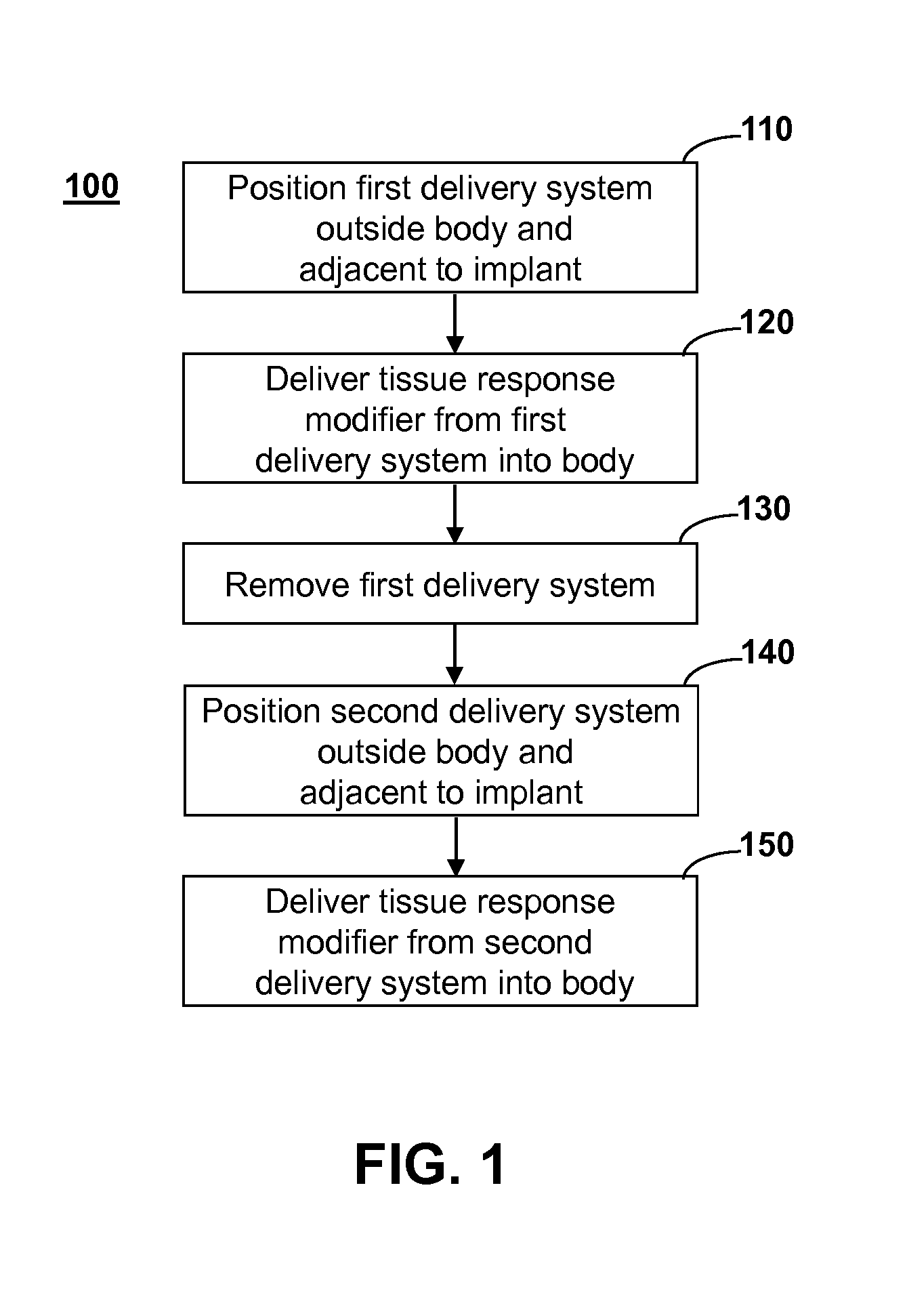
Method and system for directing a localized biological response to an implant
a biological response and implant technology, applied in the field of implants, can solve the problems of loss of analyte availability to the sensor, protein fouling of the sensor interface, and potential degradation of the sensor chemistry by enzymes
- Summary
- Abstract
- Description
- Claims
- Application Information
AI Technical Summary
Benefits of technology
Problems solved by technology
Method used
Image


Examples
example 1
[0063]Skin Preparation
[0064]Sensing Media Insertion
[0065]Post-Healing Patch
[0066]Sensor Maintenance Patch Assembly
[0067]Explant Patch
[0068]A 0.75 cm×2 cm rectangular skin preparation patch containing 300-750 μg of betamethasone, 3.5 mg / gm neomycin base, 10,000 polymyxin B units / gm, and 0.5% hydrocortisone acetate 5 mg (0.5%) is placed on the skin over the site of implantation, where it adheres to the skin by an adhesive covering the bottom surface of the patch. The drugs are contained in a section of the adhesive, and drug diffuses during the next 12-24 hours through the skin. The skin preparation patch also has a 1- to 2-mm hole near one edge that is used to guide the implantation process. The analyte sensing media, such as a 0.5 mm×10 mm rod-shaped pHEMA hydrogel implant containing analyte sensing chemicals, such as concanavalin A and dextran, or a phenylboronic-derivatized hydrogel backbone, or other reversible ligand-binding analyte pair, is inserted by syringe using the guide h...
example 2
[0069]Skin Preparation
[0070]Sensing Media Insertion
[0071]Sensor Maintenance Patch
[0072]A skin preparation patch is placed on the skin at the future implant site 6-24 hours before implantation of an implantable analyte sensor (e.g., glucose, lactate, pruvate, glycerol, urea). The skin preparatory patch contains 50-150 mg of 0.1% dexamethasone, which is released at a rate sufficient to achieve localized concentrations of 0.05-20.0 mg / kg in an area ranging from 0.5 cm to 4.0 cm in diameter and 0.05 cm to 1.0 cm in depth. The patch also contains a temporary skin colorant, e.g., 2-hydroxy-1,4-naphthoquinone (also called Henna), which will diffuse into the skin to demarcate the area that has been directly exposed to the dexamethasone. Alternatively, a wide selection of temporary transfer tattoo inks may be utilized as the temporary colorant in the skin preparatory patch. Yet another alternative for use as the temporary skin colorant is providone iodine (Betadine®), which can also steriliz...
example 3
[0077]Analyte Sensing Media Insertion
[0078]Post-Implant Healing Patch
[0079]Sensor Maintenance Patch
[0080]Analyte sensing media, such as a 0.5 mm×10 mm rod-shaped pHEMA hydrogel implant containing analyte sensing chemicals, such as concanavalin A and dextran, or a phenylboronic-derivatized hydrogel backbone, or other reversible ligand-binding analyte pair, is implanted into the dermis 0.5 mm to 5 mm below the surface of the skin by syringe or catheter. A 1.5- to 3-cm circular topical drug post-insertion healing patch containing 25 mg of 1% wt / vol of sildenafil or other nitric oxide synthase inhibitor, 10 mg of 2.5%-25% of L-arginine, and / or 2.5 mg of estradiol, is placed on the skin over the site of implantation, where it adheres to the skin by an adhesive covering the bottom surface of the patch. These drugs or agents may be contained in the entire surface adhesive, in a section of the adhesive, or in a mechanical depot within the patch with manifold orifices over the prescribed sur...
PUM
 Abstract
Description
Claims
Application Information
 - R&D
- Intellectual Property
- Life Sciences
- Materials
- Tech Scout
- Unparalleled Data Quality
- Higher Quality Content
- 60% Fewer Hallucinations
Browse by: Latest US Patents, China's latest patents, Technical Efficacy Thesaurus, Application Domain, Technology Topic, Popular Technical Reports.
© 2025 PatSnap. All rights reserved.Legal|Privacy policy|Modern Slavery Act Transparency Statement|Sitemap|About US| Contact US: help@patsnap.com