
Cast Heat-Resistant Austenitic Steel with Improved Temperature Creep Properties and Balanced Alloying Element Additions and Methodology for Development of the Same

Inactive Publication Date: 2010-12-02
UT BATTELLE LLC
View PDF5 Cites 11 Cited by
  • Summary
  • Abstract
  • Description
  • Claims
  • Application Information

AI Technical Summary

Benefits of technology

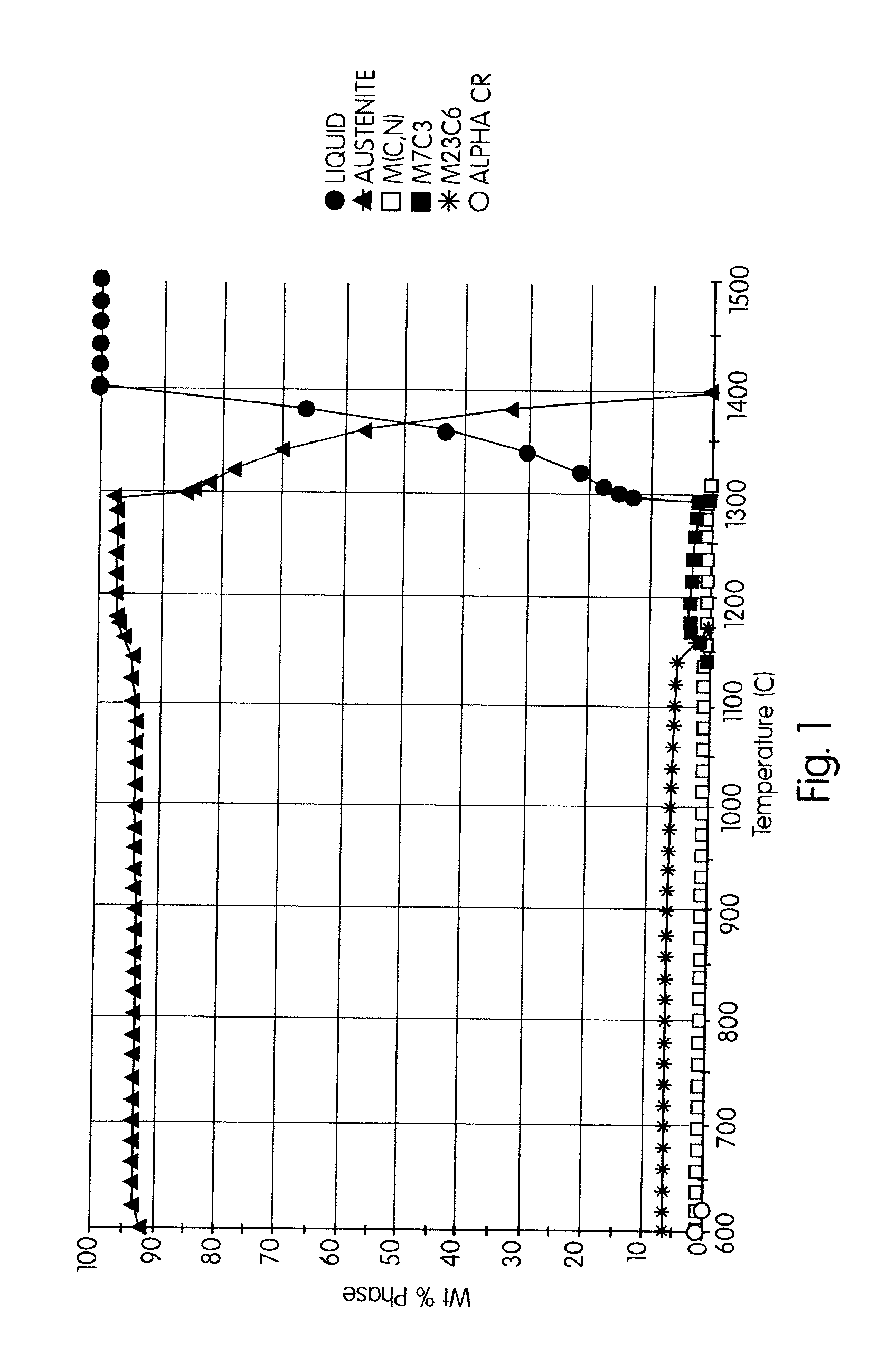
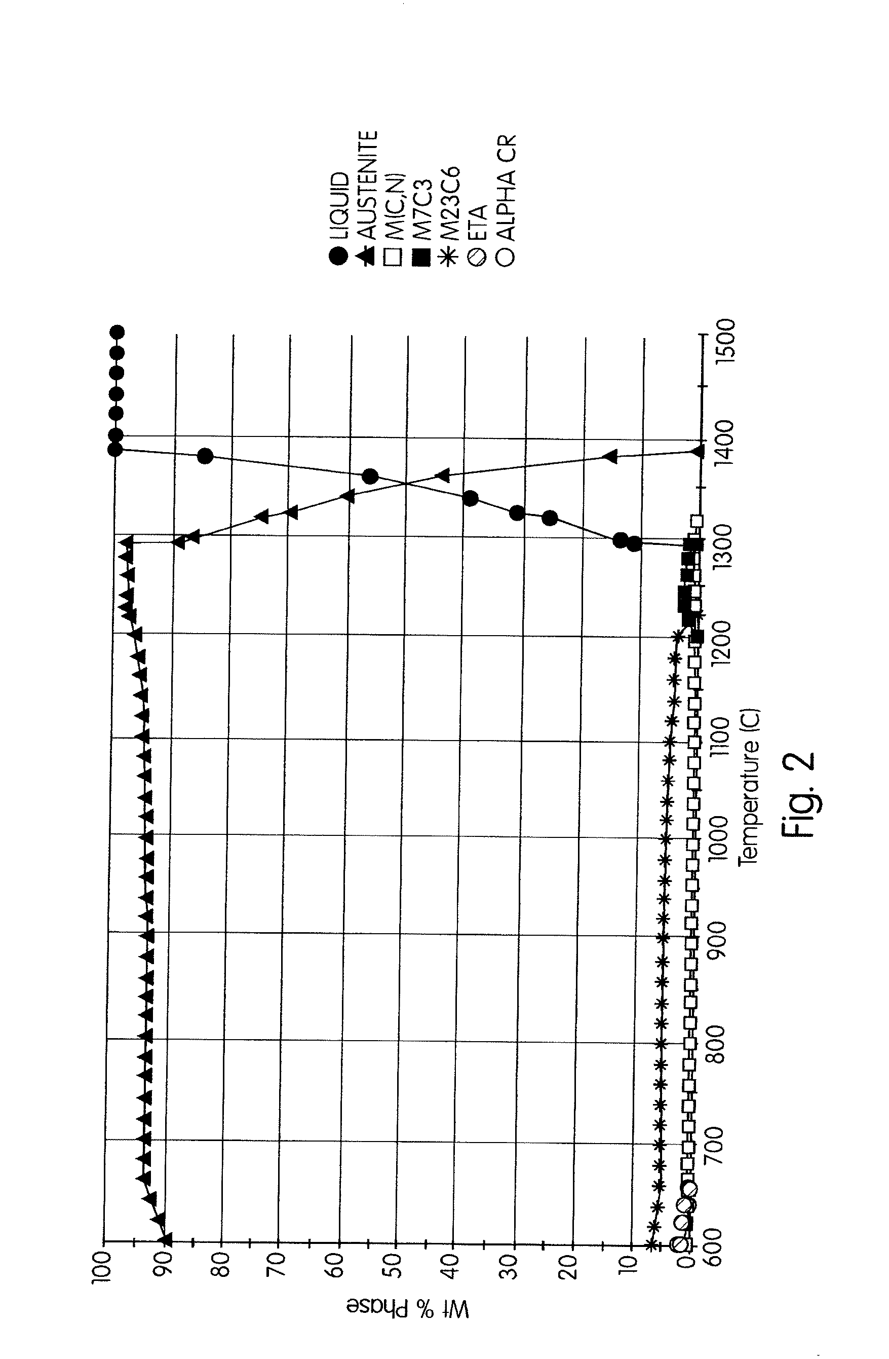
[0017]The present invention deals with the development of new cast heat-resistant austenitic alloys whose compositions are scientifically designed based on an understanding of the effect of alloying elements on the thermodynamic stabilities and compositions of various phases in the Fe—Cr—Ni alloy system. One of the unique aspects of this invention is the addition of balanced quantities of alloying elements achieved through thermodynamic calculations. These thermodynamic calculations are used to calculate the stabilities and compositions of various phases as a function of alloying element content. Using such calculations, desirable phases such as austenite, M23C6, and MC have been retained in the microstructure to higher temperatures. Moreover, the new alloys contain an optimum combination of complex carbides with alloying element additions enhancing their stability. For example, Tungsten (W) and Molybdenum (Mo) improve the stability of M23C6, while Molybdenum (Mo) and Niobium (Nb) improve the stability of MC carbides. The new compositions, when tested at about 2200° F. (1204° C.), showed improved properties when compared with standard HP and HP modified alloys.
[0019]The present invention teaches a novel methodology for the development of new cast heat-resistant austenitic alloys. The alloy compositions of the present invention were developed to primarily increase the high-temperature creep strength of existing HP- and HK-type alloys. It was determined that the presence of both types of carbides, M23C6 and MC, had a positive influence of the high-temperature creep properties of alloys. To understand the stabilities of these carbides in existing alloys, thermodynamic calculations were carried out using computational tools. The results of these calculations showed that M23C6 phase dissolution at temperatures between about 2100-2200° F. (depending on the composition of the alloy) was one of the most important factors responsible for the loss in strength. Using computational thermodynamics, the effects of adding various other elements on the stabilities of the carbide phases were determined, and additional alloying element additions were selected to increase the stability of those phases at high temperatures. In addition, alloy composition was optimized to remove or minimize expensive alloying elements such as Tungsten and Cobalt used for strengthening the matrix through solid solution strengthening in alloys such as Supertherm®. Since computational thermodynamics can predict the stability of deleterious phases such as sigma, alloy composition was also optimized to decrease the stability of that phase over the temperature range of interest.
[0021]The method of the present invention specifically includes the steps of evaluating compositions of HP and HK alloys; calculating the effect of an addition of alloying elements on the stability of M23C6 and MC utilizing thermodynamic models, using the HP and HK alloys as a base reference for the calculations, and wherein the alloying element additions are used to stabilize strengthening phases at a required temperature as indicated by the results of the thermodynamic calculations to provide improved creep-resistance.

Problems solved by technology

Although there is a need for alloys with improved high-temperature strength properties, very little work has been performed in recent times on improving the properties of H-series alloys.
One of the reasons for the lack of significant efforts is the cost and time associated with development of new alloys through traditional methods.
This work entails extensive labor, time and thus cost, with no assurance of success.
Furthermore, with multiple alloying element additions, possible permutations and combinations can be extensively large and prohibitively expensive.

Method used


Image

  • Cast Heat-Resistant Austenitic Steel with Improved Temperature Creep Properties and Balanced Alloying Element Additions and Methodology for Development of the Same
  • Cast Heat-Resistant Austenitic Steel with Improved Temperature Creep Properties and Balanced Alloying Element Additions and Methodology for Development of the Same
  • Cast Heat-Resistant Austenitic Steel with Improved Temperature Creep Properties and Balanced Alloying Element Additions and Methodology for Development of the Same

Examples


Embodiment Construction

[0033]The invention will now be described in detail in relation to the preferred embodiments and implementation thereof which is exemplary in nature and descriptively specific as disclosed. As is customary, it will be understood that no limitation of the scope of the invention is thereby intended. The invention encompasses such alterations and further modifications in the illustrated compositions and methods, and such further applications of the principles of the invention illustrated herein, as would normally occur to persons skilled in the art to which the invention relates.

[0034]As used herein in the specification and claims, including as used in the examples and unless otherwise expressly specified, all numbers may be read as if prefaced by the word “about”, even if the term does not expressly appear. Also, any numerical range recited herein is intended to include all sub-ranges subsumed therein.

[0035]And now with reference to FIGS. 1-9b, the present invention is described below...


PUM

PropertyMeasurementUnit
Temperatureaaaaaaaaaa

Abstract

The present invention addresses the need for new austenitic steel compositions with higher creep strength and higher upper temperatures. The present invention also discloses a methodology for the development of new austenitic steel compositions with higher creep strength and higher upper temperatures.

Description

PRIORITY TO PROVISIONAL APPLICATIONS[0001]This application hereby claims priority to provisional application Ser. No. 60 / 748,239, filed on Dec. 7, 2005, and provisional application Ser. No. 60 / 789,905, filed on Apr. 6, 2006. Both applications are incorporated herein by reference.STATEMENT OF FEDERAL FUNDING[0002]The United States government has rights to this invention pursuant to contract no. DE-AC05-00OR22725 between the United States Department of Energy and UT-Battelle, LLC. This invention was made under Cooperative Research and Development Agreement (“CRADA”) ORNL 02-0632 between Duraloy Technologies, Inc. and UT-Battelle, LLC.BACKGROUND OF THE INVENTION[0003]The present invention addresses the need for new austenitic steel compositions with higher creep strength and higher upper temperatures as compared to the presently used H-Series of cast stainless steels. Heat-resistant cast austenitic stainless steels and alloys are the backbone of the chemical, petrochemical, heat-treati...

Claims


Application Information

Patent Timeline
IPC IPC(8): C22C30/00G01N33/20
CPCC22C30/00C22C38/02C22C38/04
Inventor PANKIW, ROMAN I.MURALIDHARAN, GOVINDARAJANSIKKA, VINOD KUMARMAZIASZ, PHILIP J.
Owner UT BATTELLE LLC
Learn More