
High-temperature dual-source organic Rankine cycle with gas separations

a rankine turbine and gas separation technology, applied in the direction of machines/engines, lighting and heating apparatus, transportation and packaging, etc., can solve the problems of unavoidable air and moisture infiltration, cost is an order of magnitude beyond what is needed to be economically viable, and the useable temperature range of the exemplary fluid is dramatically increased, minimizing the fraction of time the fluid spends

Inactive Publication Date: 2010-12-02
DOTY SCI
View PDF43 Cites 85 Cited by
  • Summary
  • Abstract
  • Description
  • Claims
  • Application Information

AI Technical Summary

Benefits of technology

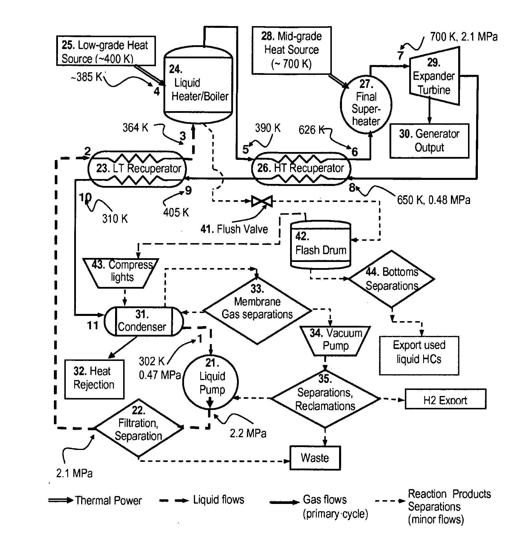
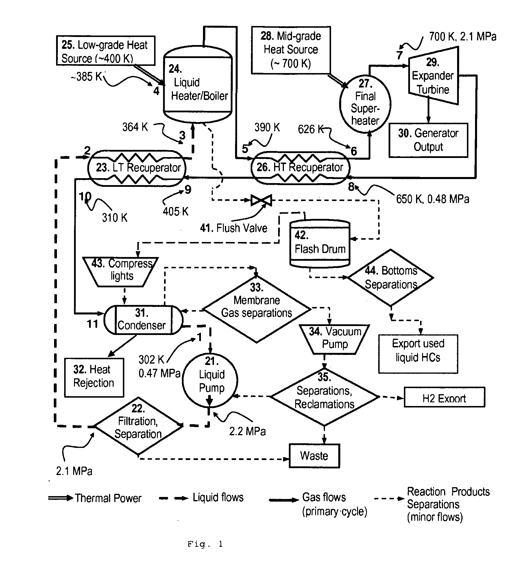
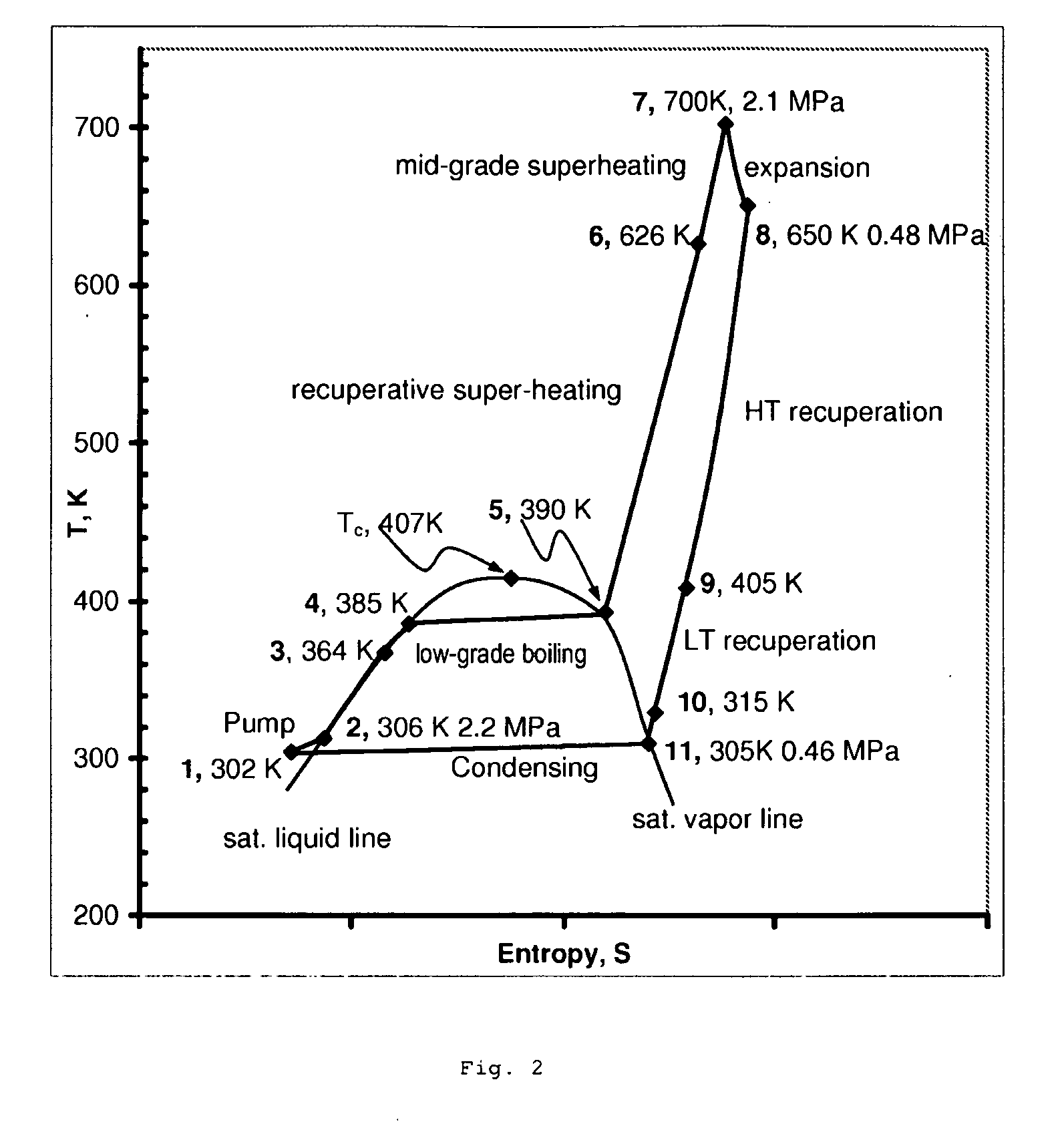
[0029]A dual-source organic Rankine cycle (DORC) is disclosed that permits substantially improved conversion of low-grade (300-500 K) and mid-grade (500-850 K) heat sources to electrical power using a single primary loop when heat is available from both sources simultaneously. The working fluid preferably has vapor pressure above 0.1 MPa at the minimum condensing temperature, mean molecular mass below 70, critical temperature near that of the low-grade heat source, and consists mostly of isobutane. The condensed and slightly sub-cooled working fluid at near ambient temperature (˜300 K) and at low-side pressure (0.1 to 0.7 MPa) is (1) pumped to high-side pressure (0.5-5 MPa), (2) pre-heated in a low-temperature (LT) recuperator, (3) boiled using a low-grade heat source, (4) super-heated in a high-temperature (HT) recuperator to a temperature close to the expander turbine exhaust temperature using this exhaust vapor enthalpy, (5) further super-heated to the turbine inlet temperature (TIT) using a mid-grade heat source, (6) expanded through a turbine expander to the low-side pressure, (7) cooled through the HT recuperator, (8) cooled through the LT recuperator, (9) mostly liquefied and slightly subcooled in a condenser, and (10) the condensed portion is returned to the pump to repeat this cycle. The minor-fraction, non-condensable gas, mostly H2, is periodically or continually separated from the condensable vapor, and heavy hydrocarbons are periodically or continually drained from the boiler. The usable temperature range of the exemplary fluid is dramatically increased by (1) accommodating hydrogen evolution from minor dehydrogenation of the alkanes; (2) periodically or continually removing undesired heavy reaction products from the fluid; (3) minimizing the fraction of time the fluid spends at high temperatures; and (4) using a mixture of mostly isobutane with minor fractions of propane, benzene, and isopentane for the working fluid.

Problems solved by technology

However, their low vapor pressures at ambient temperatures require the use of costly, cascaded cycles to avoid sub-atmospheric systems (which lead to ingress of air and moisture through unavoidable minute leaks).
The latent heat of vaporization of the working fluid and the differences in specific heats between the liquid and vapor phases make full optimization (closely approaching second-law limits) impossible for a single heat source with known working fluids.
This cost is an order of magnitude beyond what is needed to be economically viable in most cases—especially for solar, where the average power is usually under 28% of the peak power.
In this study, about two-thirds of the cost was the installation cost.
However, average efficiencies throughout the year are typically 8-18%, as both ORC and collector efficiency decrease from mid-day performance.
In the conventional ORC, the loss of expansion ratio that results from a non-condensable partial pressure in the condenser has a very detrimental effect on expander shaft power and efficiency, as the increased turbine outlet enthalpy is not usable.
The mass flow rate of the working fluid must be increased for a given output power, and the expander must continue to work efficiently at a lower expansion ratio; but these are minor technical issues.
Such attempts have achieved only 1% to 3% thermal efficiency, and thus have not been economical.

Method used


Image

  • High-temperature dual-source organic Rankine cycle with gas separations
  • High-temperature dual-source organic Rankine cycle with gas separations
  • High-temperature dual-source organic Rankine cycle with gas separations

Examples


Embodiment Construction

[0032]Fluid Chemistry Stabilization. Chemical stability is ultimately the limiting factor for DORC performance, at least when the higher-grade heat source is concentrated solar. Butanes have previously not been recommended for use above about 480 K, partly because it is assumed there may be some moist air ingress, leading to formation of organic acids and other oxygenates (the combination of copper and water very strongly catalyzes oxidation of alkanes). Heavier alkanes have often been mistakenly thought to be better suited for higher temperatures, as this trend is often seen in engine oils in oxidative environments. With no air ingress, the focus of the chemical stability problem is changed.

[0033]Table 1 lists some properties of the exemplary working fluid constituents as well as a few primary reaction products and some high-boiling organics that are preferable to some fluids previously used as the heat transfer fluid from the HT solar field to the DORC. The other popular ORC worki...


PUM


Abstract

In a dual-source organic Rankine cycle (DORC), the condensed and slightly sub-cooled working fluid at near ambient temperature (˜300 K) and at low-side pressure (0.1 to 0.7 MPa) is (1) pumped to high-side pressure (0.5-5 MPa), (2) pre-heated in a low-temperature (LT) recuperator, (3) boiled using a low-grade heat source, (4) super-heated in a high-temperature (HT) recuperator to a temperature close to the expander turbine exhaust temperature using this exhaust vapor enthalpy, (5) further super-heated to the turbine inlet temperature (TIT) using a mid-grade heat source, (6) expanded through a turbine expander to the low-side pressure, (7) cooled through the HT recuperator, (8) cooled through the LT recuperator, (9) mostly liquefied and slightly subcooled in a condenser, and (10) the condensed portion is returned to the pump to repeat this cycle.

Description

CROSS-REFERENCE TO RELATED APPLICATIONS[0001]This application claims priority from U.S. application No. 60 / 979,718, which application is incorporated herein by reference for all purposes.FIELD OF THE INVENTION[0002]The field of this invention is organic Rankine turbine power cycles. More specifically, a cycle that is optimized for efficient generation of electricity from mid-grade and low-grade heat sources when both sources are simultaneously available in comparable magnitudes, and a cycle that includes separations of reaction products from the working fluid.BACKGROUND OF THE INVENTION[0003]A large number of Rankine cycles for the production of mechanical and then electrical power from a single thermal source have been highly developed over the past century. Over the past four decades, a large number of variations have been described and evaluated for the purpose of improving the economic utilization of low-grade heat, as available from most geothermal sources, typically in the ran...

Claims


Application Information

Patent Timeline
Patent Type & Authority Applications(United States)
IPC IPC(8): F03G7/00F01K23/06F03G6/00
CPCF01K3/12F01K17/06F01K19/10F01K25/10Y02T10/166Y02E10/46Y02E20/16Y02T10/16F22G1/005Y02T10/12
Inventor DOTY, F. DAVID
Owner DOTY SCI
Learn More