
Expanded Porous Polytetrafluoroethylene Film-Laminated Sheet, and Gasket Composed of Said Sheet

a technology of porous polytetrafluoroethylene and film-laminated sheets, which is applied in the field of sheets, can solve the problems of deterioration in the productivity of sheet gaskets, film peeling, and difficult to distinguish between nodes and fibrils, so as to improve adhesiveness, improve creep resistance, and improve the effect of adhesiveness

Active Publication Date: 2010-11-11
W L GORE & ASSOC GK
View PDF6 Cites 8 Cited by
  • Summary
  • Abstract
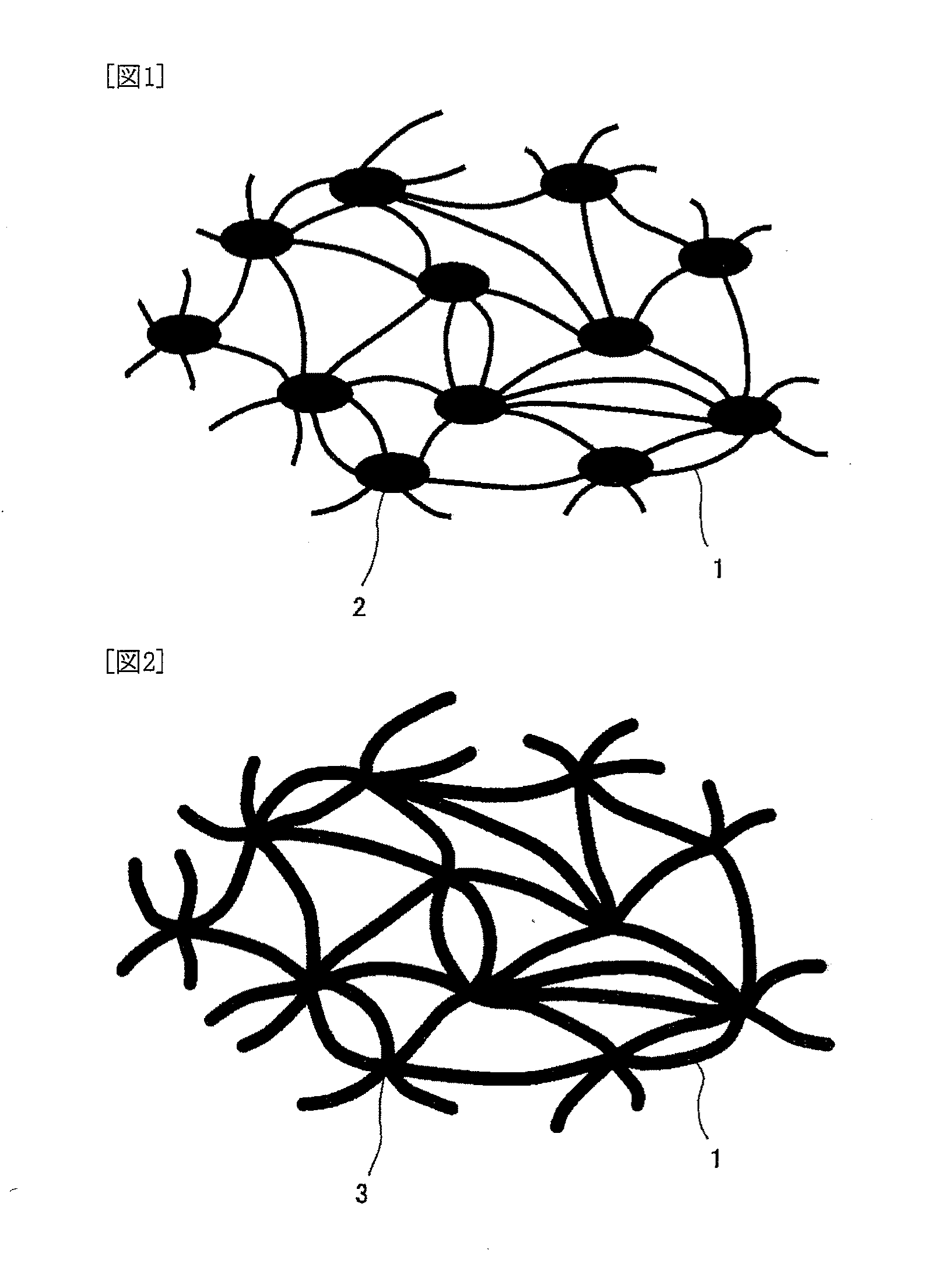
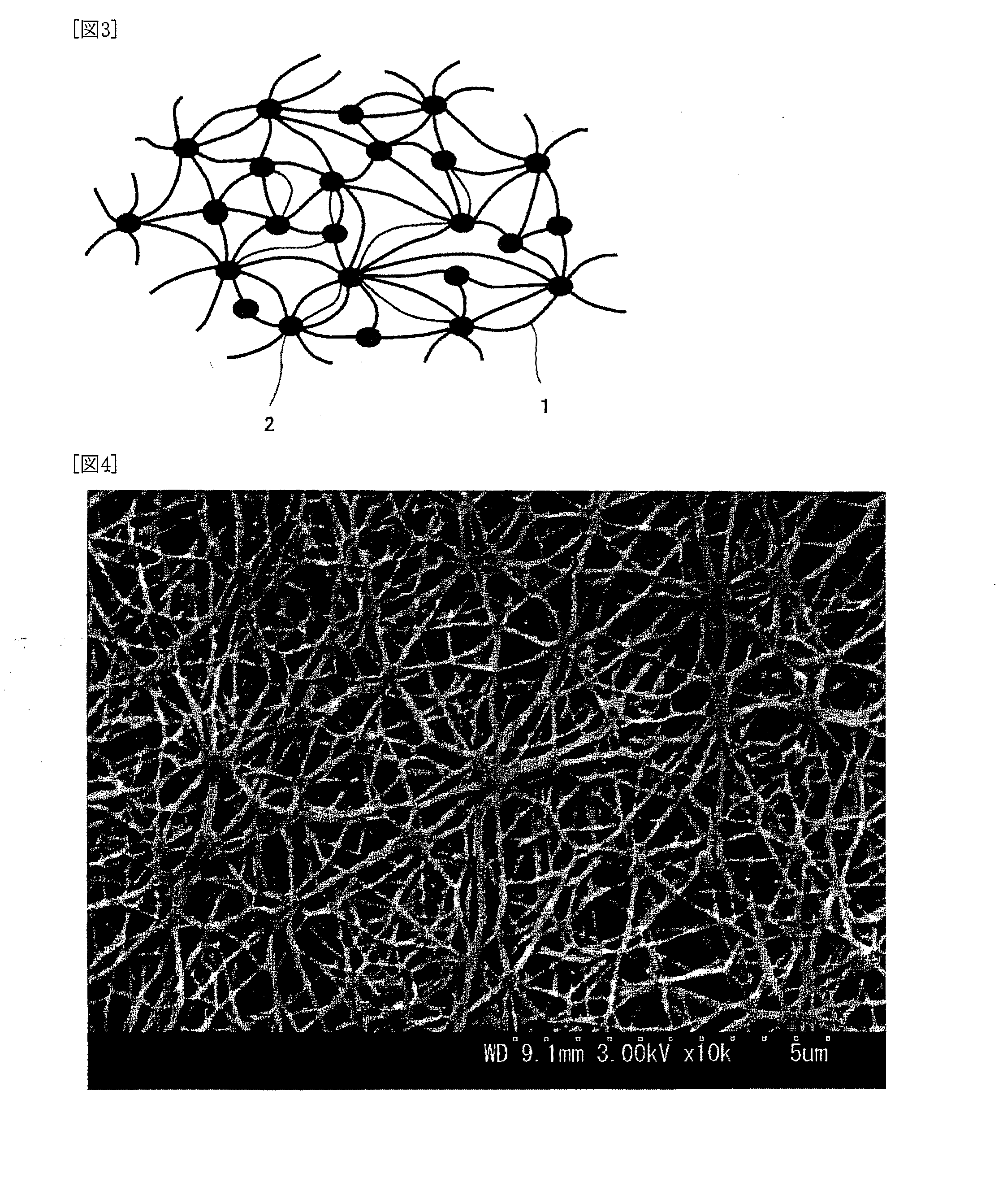
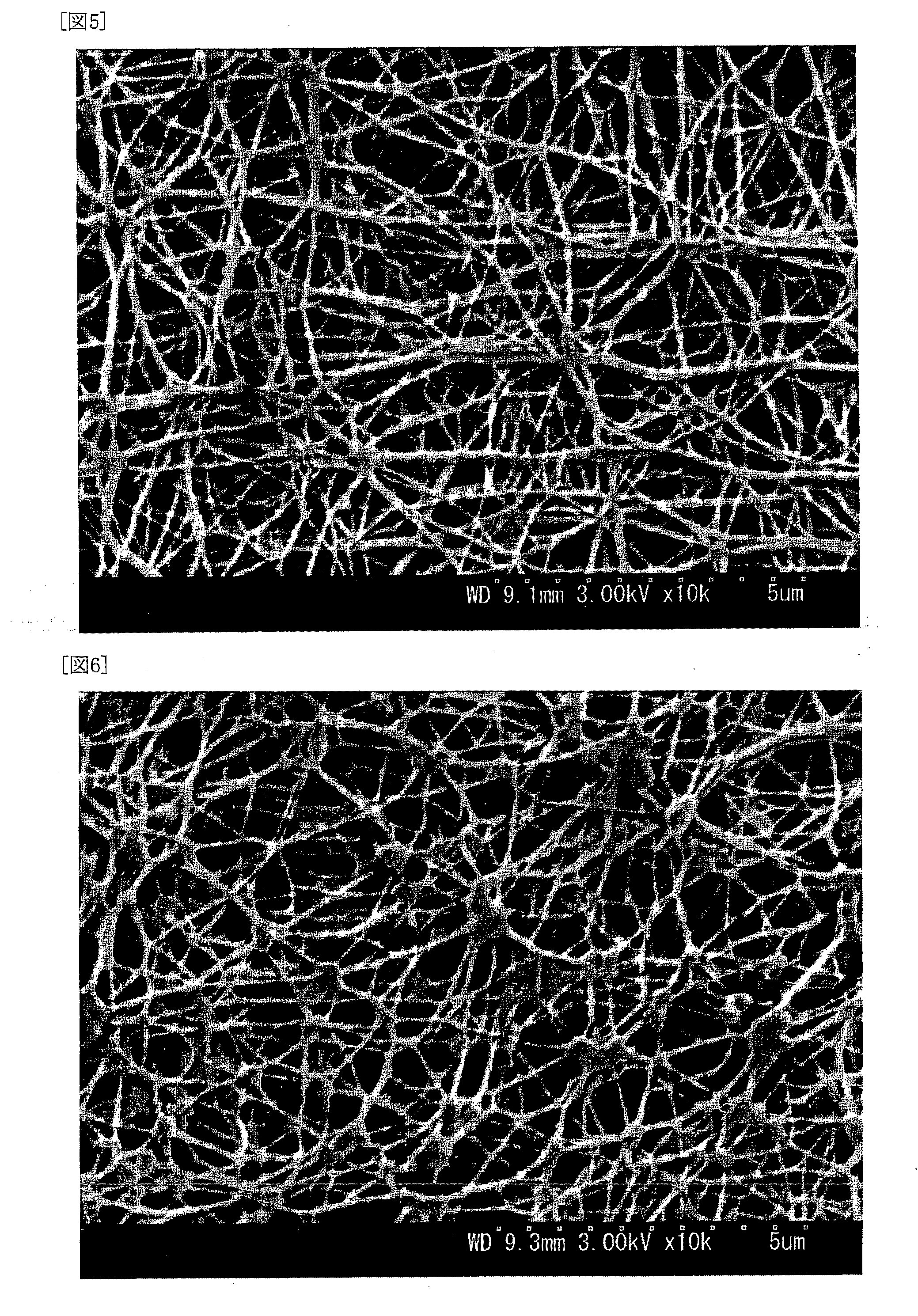
  • Description
  • Claims
  • Application Information

AI Technical Summary

Benefits of technology

[0006]This invention has been made by focusing on the situations as described above, and an object of this invention is to provide an expanded porous PTFE film-laminated sheet, which can have both improved creep resistance and improved adhesiveness between ePTFE films, and a gasket composed of this sheet.
[0007]Fibrils correspond to PTFE molecules having a high degree of crystallization, whereas nodes are in an amorphous state. These nodes are easily plastically deformed by compression stress, which causes creeping. Thus, in Japanese Patent Laid-Open Publication No. 11-80705 and Japanese Patent Laid-Open Publication No. 2006-524283, creep resistance is improved by increasing expansion ratios to make nodes as small as possible. However, it is thought that nodes play an important role in adhesion between ePTFE films. As described above, since nodes are in an amorphous state, they are softened (deformed) at lower temperatures when compared to fibrils. Therefore, when ePTFE films are laminated by thermal compression bonding, thermal bonding can be carried out, between nodes easily softened by heat, or between nodes and fibrils. The adhesiveness between ePTFE films is decreased when nodes are made small to improve creep resistance. Therefore, a further change in thinking has been needed to improve both characteristics, i.e., creep resistance and adhesiveness between ePTFE films.
[0008]The present inventors have intensively studied to solve the above-described problem, and as a result, they have found that even when the sizes of nodes are reduced to improve creep resistance, if these small nodes are generated in large numbers and the amount of fibrils is also increased, adhesiveness between ePTFE films can also be improved, while keeping improved creep resistance. However, when nodes are made small and the amount of fibrils is increased, it becomes difficult to distinguish between the nodes and the fibrils. In addition, when observed by a scanning electron microscope, a large number of nodes and fibrils are observed as being overlaid on one another in the direction of observation, and therefore, it is difficult to show this new structure directly and objectively. Thus, the present inventors have further studied, and as a result, they have found that when small nodes are generated in large numbers and the amount of fibrils is increased, the specific surface area of ePTFE is also increased, and that when the ePTFE is managed from such a viewpoint, both creep resistance and adhesiveness between ePTFE films can surely be improved. These findings have led to the completion of this invention.

Problems solved by technology

However, in the case of ePTFE sheet gaskets, since ePTFE films have very high tensile strength, if adhesiveness between ePTFE films is small, cut parts and cut residues are peeled before the cut residues are pulled and torn away, thereby causing deterioration in the productivity of the sheet gaskets.
In addition, there is also a possibility that the films may be peeled during their use as gaskets.
These nodes are easily plastically deformed by compression stress, which causes creeping.
However, when nodes are made small and the amount of fibrils is increased, it becomes difficult to distinguish between the nodes and the fibrils.
In addition, when observed by a scanning electron microscope, a large number of nodes and fibrils are observed as being overlaid on one another in the direction of observation, and therefore, it is difficult to show this new structure directly and objectively.

Method used


Image

  • Expanded Porous Polytetrafluoroethylene Film-Laminated Sheet, and Gasket Composed of Said Sheet
  • Expanded Porous Polytetrafluoroethylene Film-Laminated Sheet, and Gasket Composed of Said Sheet
  • Expanded Porous Polytetrafluoroethylene Film-Laminated Sheet, and Gasket Composed of Said Sheet

Examples


example 1

[0048]A paste obtained by adding, to a PTFE fine powder (“CD123” available from Asahi Glass Co., Ltd.), solvent naphtha as a lubricant in an amount of 17% by mass, and mixing these materials, was compressed into a cylindrical shape. The compressed product was preheated at a temperature of 60° C., and then paste extruded under the conditions that the reduction ratio (R.R.) was 160:1 and the extrusion speed was 15 m / min. After the extrusion, rolling was carried out to obtain a tape having a thickness of 0.6 mm. This tape was subjected to preliminary expansion (extension treatment) in the transverse direction, while keeping the temperature at 80° C., under the conditions that the expansion ratio was 6 times and the expansion speed was 180% / sec, and then, the lubricant was removed by drying. Then, the tape was expanded in the machine direction (length direction), while keeping the temperature at 300° C., under the conditions that the expansion speed was 400% / sec and the expansion ratio ...


PUM

PropertyMeasurementUnit
densityaaaaaaaaaa
densityaaaaaaaaaa
specific surface areaaaaaaaaaaa

Abstract

The laminated sheet of this invention is a sheet including expanded porous polytetrafluoroethylene films laminated by thermal compression bonding, wherein the sheet has a specific surface area of 9.0 m2 / g or larger and a density of from 0.4 g / cm3 to lower than 0.75 g / cm3, thereby making it possible to improve both the creep resistance and the adhesiveness between the films of the expanded porous PTFE film-laminated sheet.

Description

TECHNICAL FIELD[0001]This invention relates to a sheet obtained by laminating expanded porous polytetrafluoroethylene films (hereinafter referred to as ePTFE films) having excellent chemical resistance.BACKGROUND ART[0002]ePTFE sheets obtained by laminating expanded porous polytetrafluoroethylene films to a prescribed thickness have excellent characteristics provided by polytetrafluoroethylene materials (hereinafter referred to as PTFE), such as chemical resistance, heat resistance, purity, and smoothness. In addition, as a result of making PTFE porous by expansion, the ePTFE sheets have excellent toughness, cushioning properties, and heat insulation properties. Therefore, the ePTFE sheets have been used in various fields including cushioning materials, heat insulation materials, slide materials, and various cover materials. In particular, gaskets are one of the representative applications of the ePTFE sheets.[0003]It has been known that gaskets (hereinafter referred to as ePTFE she...

Claims


Application Information

Patent Timeline
Patent Type & Authority Applications(United States)
IPC IPC(8): F16J15/00B32B27/00B32B37/02B32B37/16
CPCF16J15/3236Y10T156/10B32B27/28B29C55/005B29L2031/265B29K2105/04B29K2027/18B32B7/10F16J15/102B32B7/12B32B27/08B32B27/14B32B27/322B32B2264/0257B32B2307/304B32B2307/518B32B2307/714B32B2307/72B32B2581/00Y10T428/249981Y10T428/249991Y10T428/249979Y10T428/249992Y10T428/249978
Inventor HISANO, HIROKAZEURAKAMI, SHINICHI
Owner W L GORE & ASSOC GK
Learn More