
Tuning Fork Oscillator Activated or Deactivated by a Predetermined Condition

a predetermined condition and oscillator technology, applied in the direction of vibration measurement in solids, material analysis through optical means, instruments, etc., can solve the problems of metal-loss corrosion of production, transfer, storage, and processing equipment, affecting the integrity of construction materials, and current corrosion sensing technologies, for example electrical resistance probes, fall far short of the performance level required to achieve the economic incentives described abov

Inactive Publication Date: 2010-11-04
EXXON RES & ENG CO
View PDF9 Cites 11 Cited by
  • Summary
  • Abstract
  • Description
  • Claims
  • Application Information

AI Technical Summary

Benefits of technology

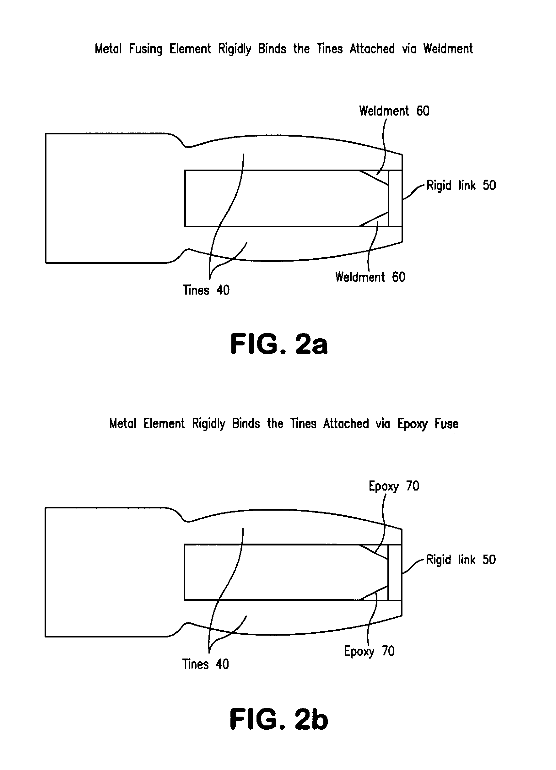
[0010]There are several embodiments to the present invention. In some embodiments, the oscillator changes from vibrating at or near resonance frequency to essentially vibrating with zero amplitude. In other embodiments, this change may be from zero amplitude to resonance amplitude. This change in the oscillation is caused by a reaction of a fusing element of the instant invention with its environment. Depending on the particular application, the fusing element may be metallic or non-metallic. In all cases, the amplitude of oscillation changes dramatically from essentially zero to resonance or resonance to essentially zero. An advantage of all these embodiments is that the alarm condition can be set without external corrections to account for changes in the oscillator resonance parameters caused by temperature, viscosity, density.

Problems solved by technology

Corrosive species involved in the production and processing of crude oil and hydrocarbons may cause metal-loss corrosion of production, transfer, storage, and processing equipment.
Other types of corrosion degradation may also occur which do not result in metal loss but which nonetheless affect the integrity of the material of construction.
Current corrosion sensing technologies, for example electrical resistance probes, fall far short of the performance level required to achieve the economic incentives described above.
Their shortcoming is that the probes' inherent signal variability caused by thermal changes, conductive deposits, and other factors that affect electrical resistance make them intrinsically unsuitable to provide a quantitative indication of material lost from corrosion / erosion.
While conventional electrical resistance probes are based on understood theoretical principles, these probes often provide low reliability and poor sensitivity to corrosion rates due to limitations in their design and manufacture.
The typical output is often difficult for estimating a quantitative corrosion rate.
A significant drawback of this approach is the safety implication of inserting or removing a coupon from an operating high temperature and / or high pressure industrial process.
Another drawback of the current technology is the time lag necessary to adequately detect and verify a change in corrosion rates which can then subject the equipment being monitored to an unnecessarily extended period of high corrosion rates before corrective measures can be implemented.
Not only is this fabrication more complicated than the instant invention, but it does not provide a procedure to precisely predetermine the change in resonance parameters or to provide an exact measure of the material loss to achieve the alarm threshold.

Method used


Image

  • Tuning Fork Oscillator Activated or Deactivated by a Predetermined Condition
  • Tuning Fork Oscillator Activated or Deactivated by a Predetermined Condition
  • Tuning Fork Oscillator Activated or Deactivated by a Predetermined Condition

Examples


Embodiment Construction

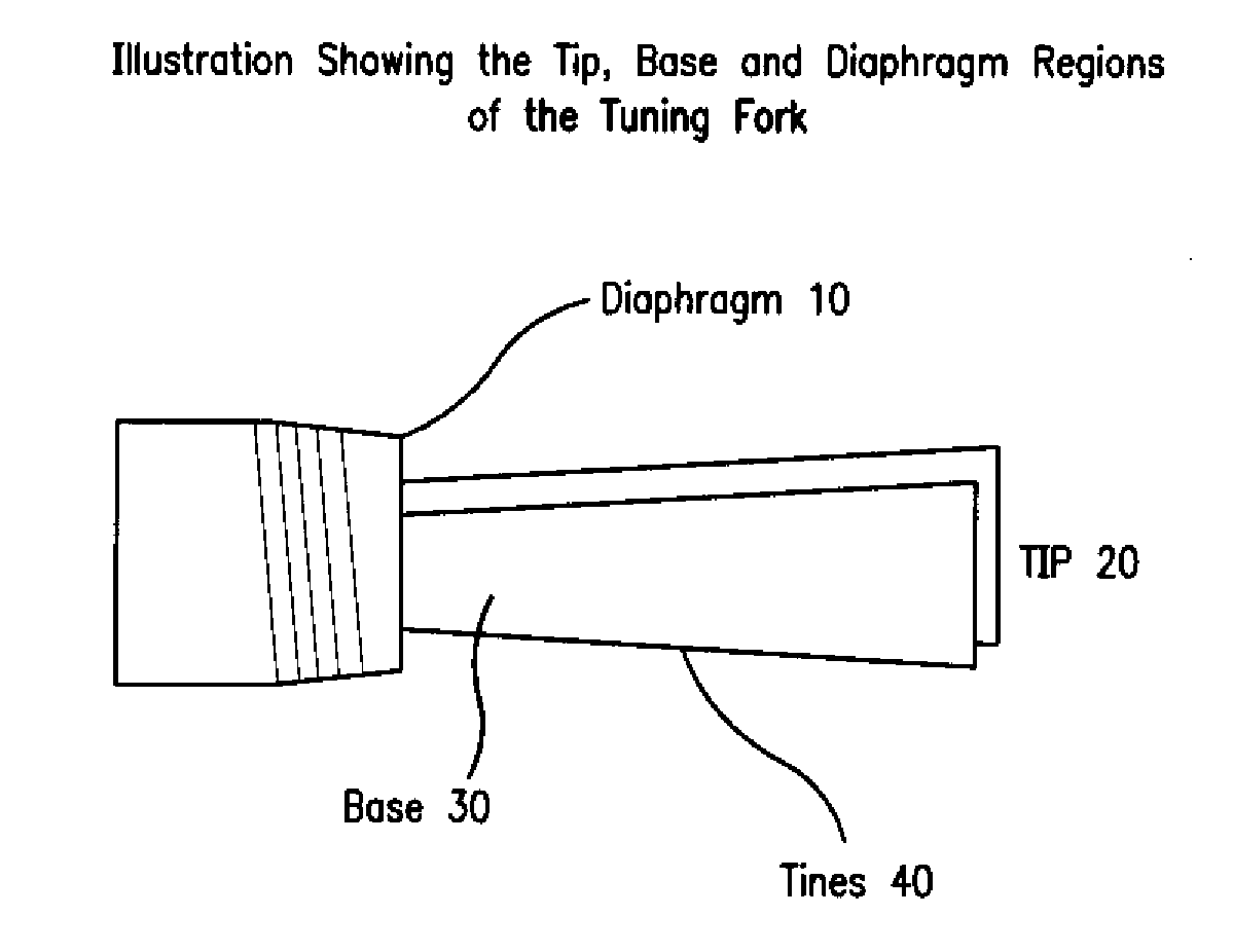
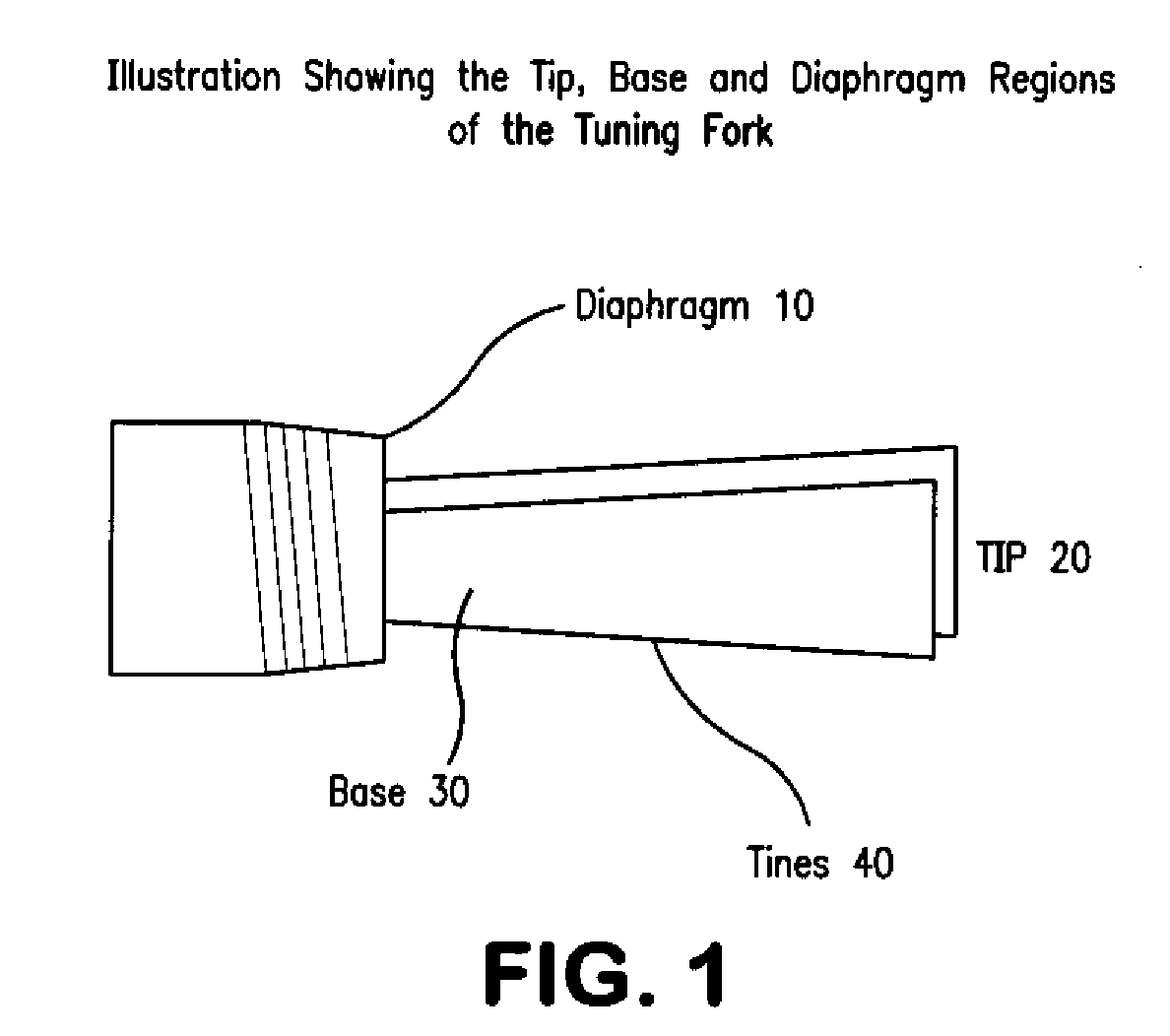
[0024]This invention is directed to commercial tuning fork technology. As shown in FIG. 1, the tuning fork consists of a two tines [40] attached to a diaphragm [10]. The tines are comprised of a tip [20] and a base [30] region. Various shapes are possible for the tines including round, hemi-cylindrical, and a non-uniform shape for the tip and base region. The existing commercial applications include the on-line in-situ measurement of fluid level, density and / or viscosity of process streams in a wide range of industries. The instant invention involves the measurement of changes in the resonant parameters (in particular amplitude) of a tuning fork immersed in a process stream to detect material loss. The current commercially available devices use the resonance parameters of frequency, Q, and amplitude to determine the density and the viscosity of the medium. The underlying assumption in these devices for measuring fluid level, density and / or viscosity is that the mass of the oscillato...


PUM


Abstract

The present invention is a tuning fork oscillator for detection and measurement of corrosive or foreign materials. The elements include a means for mechanical excitation, and a mechanical oscillator, wherein said mechanical oscillator has a resonant frequency, f, and a quality factor, Q. A fuse fixed to the oscillator to change oscillator amplitude to or from essentially zero to resonance amplitude. In a preferred embodiment, the tuning fork has one region compatible with the service fluid and the other region is incompatible with the service fluid or other contaminant. The sensor alarms when a measured amount of the incompatible material has been removed or deposited.

Description

[0001]This application is a Continuation-In-Part Under 37 C.F.R. §1.53(b) of U.S. Ser. No. 12 / 156,576, filed Jun. 3, 2008 which claims the benefit of U.S. Provisional Application 60 / 934,711 filed Jun. 15, 2007.BACKGROUND OF THE INVENTION[0002]The present invention relates to the detection and measurement of corrosive or foreign materials. The invention may be applied generally to the detection of metal-loss by corrosion and / or erosion and / or deposition species in single or multiphase fluids. In particular, the present invention relates to the on-stream detection of metal-loss corrosion and / or erosion and / or deposition during an industrial production process. In other embodiments, the invention may be used to detect unwanted contaminants in an industrial process stream. The actual service environment may be aqueous, hydrocarbon, chemical, or a combination thereof.[0003]Corrosive species involved in the production and processing of crude oil and hydrocarbons may cause metal-loss corro...

Claims


Application Information

Patent Timeline
IPC IPC(8): G01N29/12
CPCG01N17/04G01N17/00G01N2291/0258G01N29/12
Inventor WOLF, HENRY A.ALVAREZ, MANUEL S.FEATHER, JAMES E.YABLON, DALIASCHILOWITZ, MARK A.GRABOWSKI, JEAN
Owner EXXON RES & ENG CO
Learn More