
Method for manufacturing a quartz crystal unit

Inactive Publication Date: 2005-05-31
PIEDEK TECHN LAB
View PDF8 Cites 42 Cited by
  • Summary
  • Abstract
  • Description
  • Claims
  • Application Information

AI Technical Summary

Benefits of technology

[0009]It is an object of the present invention to provide a quartz crystal unit with a miniaturized flexural mode, tuning fork, quartz crystal resonator with a small series resistance R1 and a high quality factor Q.
[0010]It is an another object of the present invention to provide a quartz crystal unit with a flexural mode, tuning fork, quartz crystal resonator with an excellent frequency temperature behaviour over a wide temperature range (of −10° C. to +50° C.).
[0018]Embodiments of the present invention may provide a high electromechanical transformation efficiency.
[0022]Preferably, at least two individual flexural mode, tuning fork, quartz crystal resonators connected and formed integrally at their respective tuning fork base via connecting portion may improve the frequency temperature behaviour. The quartz crystal resonators whose peak temperature points are different, may be connected electrically in parallel. As a result, the integrally formed quartz crystal resonator may have excellent frequency temperature behaviour over a wide temperature range of −10° C. to +50° C.

Problems solved by technology

It is, however, impossible to obtain a miniaturized quartz crystal unit with a conventional miniaturized, flexural mode, tuning fork, quartz crystal resonator with a small series resistance and a high quality factor.
In addition, it is impossible to obtain a flexural mode, tuning fork, quartz crystal resonator with a small frequency change over a wide temperature range of between −10° C. to +50° C. because the resonator has a temperature coefficient with a parabolic curve, and whose second order temperature coefficient is approximately −3.5×10⁻⁸ / ° C.2.

Method used


Image

  • Method for manufacturing a quartz crystal unit
  • Method for manufacturing a quartz crystal unit
  • Method for manufacturing a quartz crystal unit

Examples


second embodiment

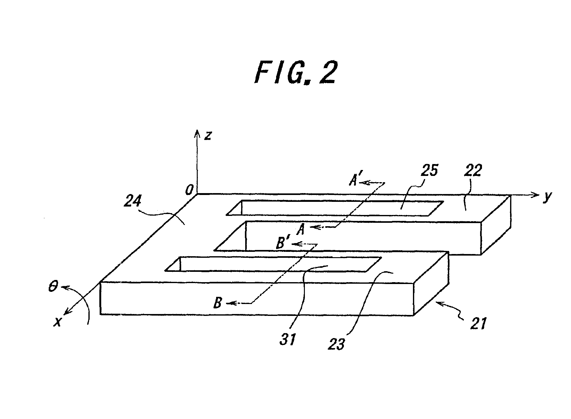
[0069]FIG. 5 shows a general view of a flexural mode, tuning fork, quartz crystal resonator 69 which constructs a quartz crystal unit of the present invention and its coordinate system O-xyz. A cut angle θ, which has a typical value of 0° to 10°, is rotated from a Z-plate perpendicular to the z axix about the x axis. The flexural mode, tuning fork, quartz crystal resonator 69 comprises two tuning fork tines 70 and 76 and tuning fork base 90. The tuning fork tines 70 and 76 have grooves 71 and 77 respectively, with the grooves 71 and 77 extending into the tuning fork base 90. In addition, the tuning fork base 90 has the additional grooves 82 and 86.

[0070]FIG. 6 shows a D-D′ cross-sectional view of the tuning fork base 90 for the flexural mode, tuning fork, quartz crystal resonator 69 of FIG. 5. In FIG. 6, the shape of the electrode construction within the tuning fork base 90 for the quartz crystal resonator of FIG. 5 is described in detail. The section of the tuning fork base 90 whic...

third embodiment

[0075]FIG. 8 shows a plan view of a flexural mode, tuning fork, quartz crystal resonator 145 which constructs a quartz crystal unit of the present invention. The flexural mode, tuning fork, quartz crystal resonator 145 comprises tuning fork tines 146, 147 and tuning fork base 148. At least one end of the tuning fork tines 146 and 147 connected to the tuning fork base 148. In this embodiment, a plurality of grooves 149, 150, 151 and 152 are constructed only within the tuning fork base 148. Additionally, a plurality of grooves is similarly constructed within the reverse face of tuning fork base 148.

[0076]In addition, the grooves 149 and 150 are constructed within the tuning fork base 148 where at least one end of the tuning fork tines 146 and 147 is connected to the tuning fork base 148. Furthermore, the grooves 151 and 152 are constructed between the grooves 149 and 150. The electrode disposition and the construction is not shown, but is similar to that already explained in detail in...

fourth embodiment

[0077]FIG. 9 shows a plan view of a flexural mode, tuning fork, quartz crystal resonator 153 which constructs a quartz crystal unit of the present invention. The quartz crystal resonator of tuning fork type 153 comprises the tuning fork tines 154, 155 and the tuning fork base 156. The tuning fork tines 154 and 155 have grooves 157 and 158 which extend to the tuning fork base 156. In addition, a groove 159 constructed between the grooves 157 and 158 and constructed within the tuning fork base 156.

[0078]FIG. 10 shows F-F′ cross-sectional view of the tuning fork base 156 for the flexural mode quartz crystal resonator 153 of FIG. 9. Here, the shape and the electrode construction of the cross-sectional view of the tuning fork base 156 for the quartz crystal resonator 153 in FIG. 9 are described in detail. As shown in FIG. 10, the quartz crystal resonator 153 has grooves 157 and 160 within the obverse and the reverse faces of the tuning fork base 156 where it connects to the tuning fork t...


PUM

PropertyMeasurementUnit
Fractionaaaaaaaaaa
Fractionaaaaaaaaaa
Fractionaaaaaaaaaa

Abstract

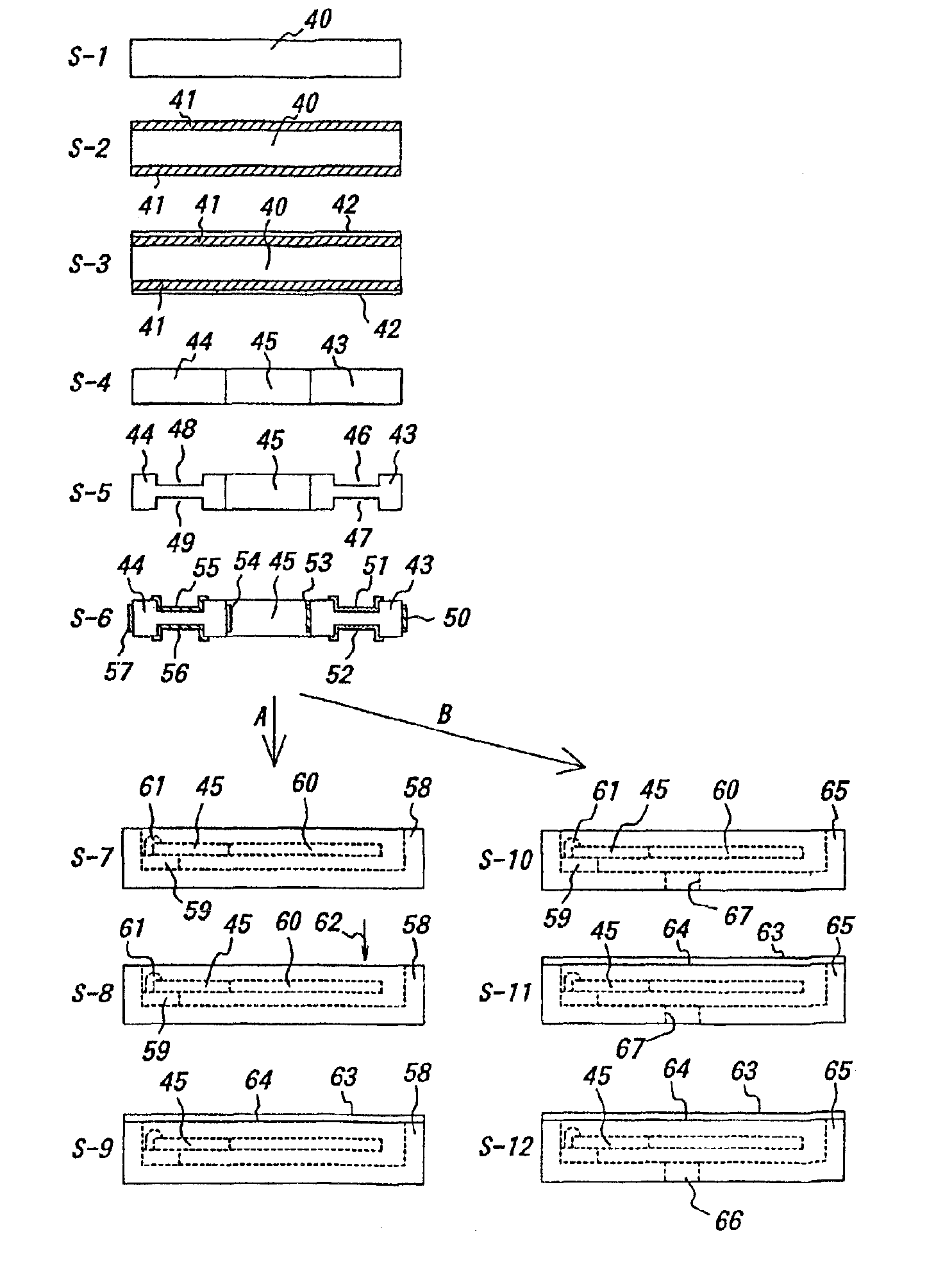
In a method for manufacturing a quartz crystal unit, a quartz crystal tuning fork resonator is formed by etching a quartz crystal wafer to form a quartz crystal tuning fork base, quartz crystal tuning fork tines connected to the quartz crystal tuning fork base, and a groove having stepped portions in at least one of opposite main surfaces of each of the quartz crystal tuning fork tines. A first electrode is disposed on at least one of the stepped portions of each of the grooves and a second electrode is disposed on each of side surfaces of each of the quartz crystal tuning fork tines. A frequency of oscillation of the quartz crystal tuning fork resonator is adjusted at least twice and in different steps. The quartz crystal tuning fork resonator is then mounted in a case and an open end of the case is covered with a lid.

Description

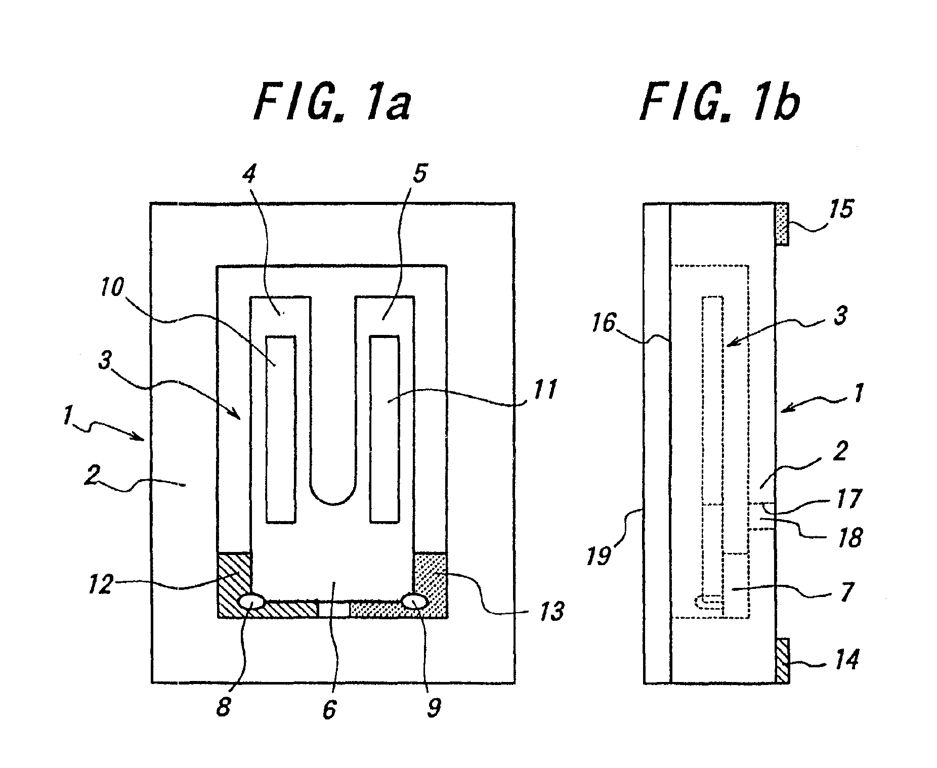
BACKGROUND OF THE INFORMATION[0001]The present invention relates to a quartz crystal unit comprising a flexural mode, tuning fork, quartz crystal resonator, a case and a lid, and its manufacturing method.BACKGROUND INFORMATION[0002]Quartz crystal units with a tuning fork, quartz crystal resonator which vibrates in flexural mode are widely used as a time standard in consumer products, wearable equipment and communication equipment (such as wristwatches, cellular phones, and pagers). Recently, because of miniaturization and the light weight nature of these products, a smaller quartz crystal unit with a smaller flexural mode, tuning fork, quartz crystal resonator is required with a small series resistance and a high quality factor.[0003]FIG. 28(a) and FIG. 28(b) show a plan view and a side view of a quartz crystal unit 101 with the conventional flexural mode, tuning fork, quartz crystal resonator 100. The resonator 100 comprises tuning fork tines 102, 103 and tuning fork base 104. The ...

Claims


Application Information

Patent Timeline
IPC IPC(8): H03H9/00H03H9/215H03H9/10H03H9/05H01L41/09H01L41/18H01L41/22H01L41/23H01L41/253H01L41/29H01L41/313H03H3/04H03H9/19
CPCH03H9/1021H03H9/21H03H9/1014H03H9/105H03H3/02H03H9/1035H03H9/215Y10T29/49574H03H2003/026H03H2003/0492Y10T29/42Y10T29/49005Y10T29/49128Y10T29/49126Y10T29/49004
Inventor KAWASHIMA, HIROFUMI
Owner PIEDEK TECHN LAB
Learn More