
CMP conditioner and method of manufacturing the same

a conditioner and conditioner technology, applied in the field of chemical mechanical polishing conditioners, can solve the problems of increasing the self-weight of the conditioner, reducing the polishing speed or irregular polishing, and affecting the polishing effect, so as to reduce the deformation of the metal plate, increase the strength of the contacting surface of the cmp conditioning pad, and reduce the effect of external for

Inactive Publication Date: 2010-10-28
MITSUBISHI MATERIALS CORP
View PDF0 Cites 19 Cited by
  • Summary
  • Abstract
  • Description
  • Claims
  • Application Information

AI Technical Summary

Benefits of technology

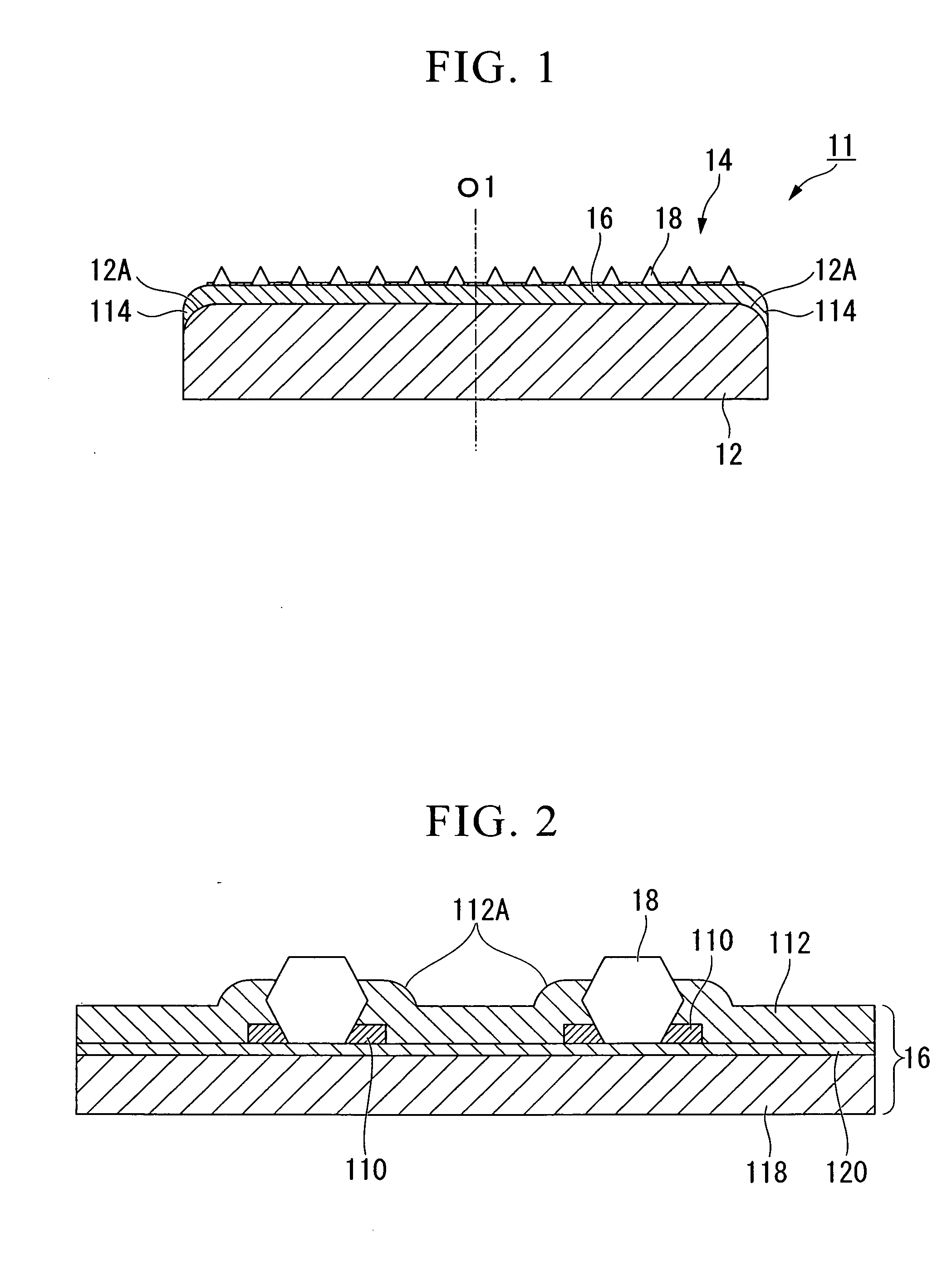
[0013]According to an aspect of the invention, there is provided a chemical mechanical polishing (CMP) conditioner in which diamond abrasive grit is adhered to a conditioning surface which faces and makes contact with an abrasive pad of a CMP machine, wherein the diamond abrasive grit is adhered to the CMP conditioner body by a metal plating layer, and the CMP conditioner body is formed of resin. The metal plating layer including the diamond abrasive grit and the CMP conditioner body are provided as separate components and bonded as a single body. In this case, it is possible to make the CMP conditioner be lightweight, suppress generation of internal cracks by a thermal impact or the like, and adhere the diamond abrasive grit to the CMP conditioner body at a regularly-spaced interval.
[0014]According to another aspect of the invention, an outer peripheral end portion of the metal plating layer is provided with a curved portion curved in a thickness direction of the metal plating layer along a side surface of the CMP conditioner body around the entire periphery. In this case, the rigidity of the metal plating layer increases, and flatness in the conditioning surface is obtained. Since the diamond abrasive grit is adhered to the conditioning surface at a regularly-spaced interval, it is possible to prevent slurries from being soaked from the outer peripheral portion to the bonding surface and to contribute to the bonding strength.

Problems solved by technology

Thereby, undesirable phenomena such as polishing speed reduction or irregular polishing occur.
However, since stainless steel or ceramics are usually used in the body of the aforementioned CMP conditioner to provide an anticorrosion property, the self-weight of the conditioner increases, making it difficult to perform precisely controlled conditioning.
However, in a case of the resin body, although the CMP conditioner can be made in a lightweight, the resin tend to be removed easily during the conditioning if the diamond abrasive grits are directly adhered to the resin body.
This characteristic adversely affects conditioning performance of the conditioner.
Although the diamond abrasive grits can be directly adhered to the resin using an electroplating layer, they may drop off due to an insufficient adhesive force.
Although the diamond abrasive grits can be adhered using a sintering bond as an alternative method, it is disadvantageous comparing to the adhesion using the electroplating layer because of higher cost.
In addition, the diamond abrasive grits could be fractured, since minute cracks can be generated within the diamond abrasive grits by a thermal shock.

Method used


Image

  • CMP conditioner and method of manufacturing the same
  • CMP conditioner and method of manufacturing the same
  • CMP conditioner and method of manufacturing the same

Examples


first embodiment

[0055]Hereinafter, an embodiment of the present invention is described in detail. FIG. 1 schematically illustrates a CMP conditioner 11 according to an embodiment of the present invention. The CMP conditioner 11 includes a body 12 having a circular disc shape with respect to the axial line O1, a metal plating layer 16, and diamond abrasive grits 18. The body 12 may be formed of resin, and preferably, of polyphenylene-based resin materials having a glass-transition temperature of 211° C. and a water absorption coefficient of 0.050% such as PPE and PPS. Further, the metal plating layer 16 includes a base plating layer 118, a Ni-strike plating layer 120, an underlying plating layer 110, and a buried plating layer 112. A coating layer (not shown) may be further provided on the buried plating layer 112.

[0056]A peripheral edge 12A of a surface facing to an abrasive pad (not shown) of the body 12 is chamfered in an R-shape around the entire circumference. The metal plating layer 16 is prov...

second embodiment

[0076]Referring to FIGS. 5 and 6, the CMP pad conditioner 21 according to the second embodiment of the present invention includes a base body 22 which has a circular disc shape and rotates with respect to the axial line O2 and a metal plating plate (or metal plate) 26 which is disposed on the base body 22 and has a circular disc shape with the diamond abrasive grits (or cutting blade) 28 being protruded on the surface 26A. The CMP pad conditioner 21 is used in the CMP machine to perform a grinding process by the diamond abrasive grits 28 on the CMP pad (not shown) disposed to face the surface 26A of the metal plating plate 26. The CMP pad is used to polish semiconductor wafers.

[0077]The base body22 and the metal plating plate 26 are bonded to each other with the adhesive B2. According to the second embodiment of the present invention, a two-liquid mixed type is used as the adhesive B2.

[0078]The base body 22 is formed on a resin material such as engineering plastics. According to the...

third embodiment

[0119]Next, the third embodiment of the present invention will be described with reference to FIGS. 10 and 11. The reference numerals in the aforementioned embodiments are used to the same members in this embodiment, and descriptions thereof will be omitted.

[0120]The CMP pad conditioner 211 according to the third embodiment is different from the CMP pad conditioner 21 of the aforementioned embodiment in that the protrusions 23 are set such that the areas of the leading ends increase gradually from the center to the outer circumference on the provided surface 22A thereof.

[0121]Referring to FIG. 10, a plurality of protrusions 23 having a circular column shape of a circular disc shape are provided on the surface 22A of the base body 22, and these protrusions 23 have the same shape. In addition, in the CMP pad conditioner 211 of the present embodiment, the protrusions 23 are arranged gradually densely from the center to the outer circumference in a radial direction on the surface 22A.

[0...


PUM

PropertyMeasurementUnit
Fractionaaaaaaaaaa
Thicknessaaaaaaaaaa
Ratioaaaaaaaaaa

Abstract

A chemical mechanical polishing (CMP) conditioner has diamond abrasive grits adhered to a conditioning surface which faces and makes contact with an abrasive pad of a CMP machine. The diamond abrasive grit is adhered to the CMP conditioner body by a metal plating layer, and the CMP conditioner body is formed of resin.

Description

BACKGROUND OF THE INVENTION[0001]1. Field of the Invention[0002]The present invention relates to a chemical mechanical polishing (CMP) conditioner used for conditioning (dressing or toothing) of an abrasive pad of the CMP machine for polishing semiconductor wafers, and a method of manufacturing the same.[0003]Priority is claimed on Japanese Patent Application Nos. JP 2009-107858 and JP 2009-158619 filed in the Japan Patent Office on Apr. 27, 2009, and Jul. 3, 2009, respectively, the content of which is incorporated herein by reference.[0004]2. Description of Related Art[0005]As the semiconductor industry advances, demands for a machining method for polishing surfaces of metals, semiconductors, ceramics, or the like with a high precision soar. Particularly, as integration on semiconductor wafers increases, there is a demand for surface polishing of a nanometer order. In order to provide such high-precision surface polishing, a chemical mechanical polishing (CMP) process using a porou...

Claims


Application Information

Patent Timeline
IPC IPC(8): B24B1/00B24B55/00
CPCB24B53/017B24D18/00B24B53/12
Inventor SHIMIZU, AKIHIRO
Owner MITSUBISHI MATERIALS CORP
Learn More