
Novel cascaded power plant process and method for providing reversibly usable hydrogen carriers in such a power plant process

a power plant and cascade technology, applied in the direction of silicates, silicon compounds, separation processes, etc., can solve the problems of ineffective and expensive separation methods applied to oil and minerals, and achieve the effect of improving the efficiency and rapidity of hydrolysis of silicon nitride, and improving the suitability of the process

Inactive Publication Date: 2010-09-30
SILICON FIRE AG
View PDF13 Cites 3 Cited by
  • Summary
  • Abstract
  • Description
  • Claims
  • Application Information

AI Technical Summary

Benefits of technology

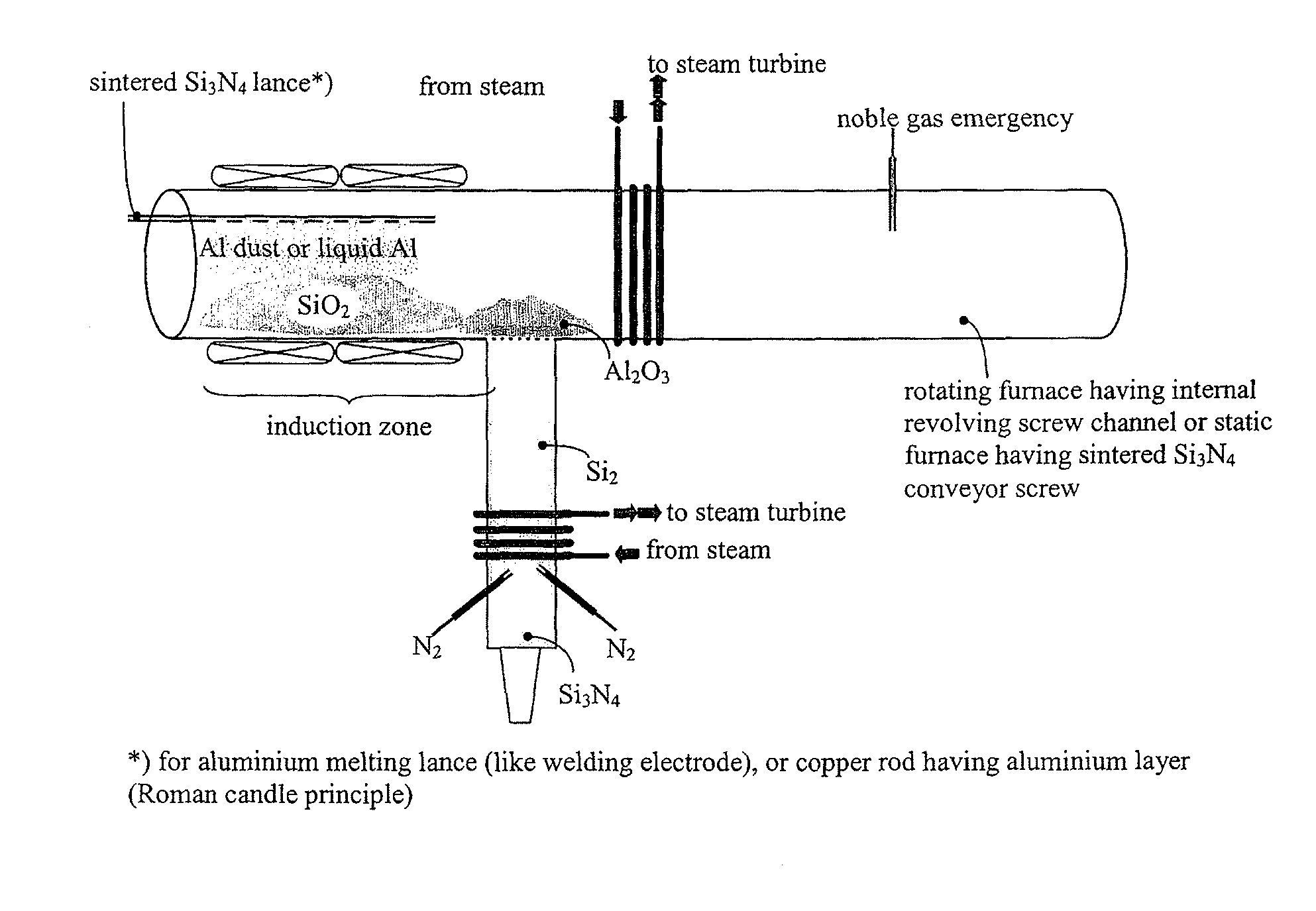
[0019]According to the present invention, in a first partial reaction in a power plant process, silicon is obtained from one or more of the following starting materials: oil sand, oil shale, bauxite, gneiss, mica, granite, or slate. The use of the number “1” is not to indicate that this partial reaction is executed first. A blend of one or more of the cited starting materials is possibly used in the scope of this first partial reaction, which is liquefied by adding an acid or base, to improve the transportability through pipes, for example. In this case, the acid or base may be reclaimed again by the heating using the primary energy providers.
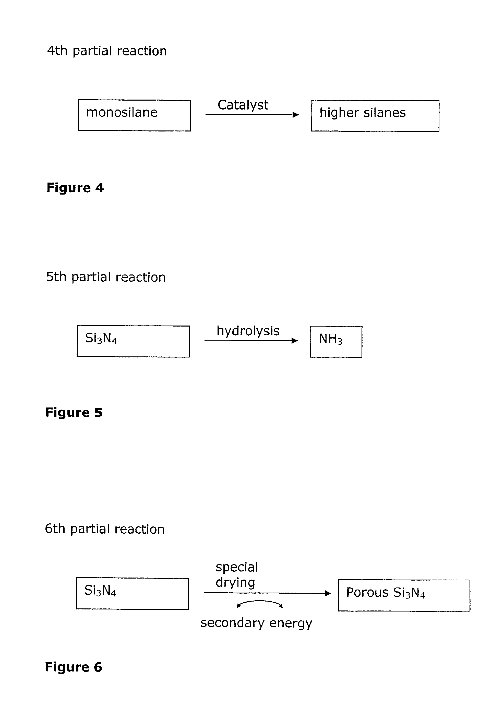
[0024]Thus, NH3 and silicon dioxide arise in this reaction. NH3 is an outstanding hydrogen carrier. Because the hydrolysis of silicon nitride runs relatively slowly, the silicon nitride is used according to the present invention either as flakes, as a powder, or in porous form. A significantly larger surface thus results, which makes the hydrolysis of the silicon nitride much more efficient and rapid. This approach is based on the finding that in the hydrolysis of silicon nitride, surface hydrolysis plays an essential role. The hydrolysis thus becomes more efficient due to the intentional enlargement of the surface of the silicon nitride. The reaction of silicon nitride to form NH3 using hydrolysis is referred to here as the fifth partial reaction. The use of Si3N4 nanostructures or nanocrystals is especially effective here, which may be obtained from a sol-gel process, for example. The energy for the sol-gel process may in turn be taken from one of the partial reactions according to the present invention.

Problems solved by technology

The technical methods applied for separating oil and minerals are currently ineffective and too costly.

Method used


Image

  • Novel cascaded power plant process and method for providing reversibly usable hydrogen carriers in such a power plant process
  • Novel cascaded power plant process and method for providing reversibly usable hydrogen carriers in such a power plant process
  • Novel cascaded power plant process and method for providing reversibly usable hydrogen carriers in such a power plant process

Examples


first embodiment

[0093]A first embodiment is shown in FIG. 16. As may be seen in FIG. 16, two vertically operating combustion furnaces 10 and 20 (e.g., blast furnaces) are situated neighboring one another. The first combustion furnace 10 has an outlet area 11 and the second combustion furnace 20 has an outlet area 21 for the exhaust gases (flue gas) arising in each case. The first combustion furnace is charged with a fossil fuel 12 (e.g., hard coal) and the fossil fuel is combusted using oxygen (e.g., air oxygen). A large quantity of heat is released during this method, which is known per se, which is partially transferred via a heat exchanger 13 to a medium (e.g., water), to drive turbines and thus obtain current using the resulting water steam.

[0094]According to the present invention, the various reactions run in a cascade. In the exemplary embodiment shown, there is a heat coupling to the second combustion furnace 20, i.e., the two furnaces 10 and 20 are directly or indirectly thermally coupled t...

second embodiment

[0099]A second embodiment is shown in FIG. 17. As shown in FIG. 17, a vertically operating combustion furnace 20 is provided. One of the starting materials 22 containing the silicon dioxide is heated in the combustion furnace 20 by the combustion of a primary energy provider (e.g., fossil fuels such as oil and / or tar). Inter alia, silicon arises in this first partial reaction of the present invention. Analogously to the first exemplary embodiment, silicon nitride and heat arise due to the introduction of nitrogen. However, in an alteration of this process, the silicon may also react with carbon to form SiC (see tenth partial reaction). The carbon may originate from the fossil fuels or from CO2, which may be optionally introduced into the furnace 20 (e.g., by a supply 25). This partial reaction also runs exothermically, but delivers significantly less heat than the second partial reaction.

[0100]CO2 may also be introduced into the furnace 20 in the second embodiment, as noted.

[0101]A ...

third embodiment

[0103]A third embodiment is shown in FIG. 18. As may be seen in FIG. 18, a vertically operating combustion furnace 20 is provided. One of the starting materials 22 containing the silicon dioxide is heated in the combustion furnace 20 by the combustion of a primary energy provider (e.g., fossil fuels such as oil and / or tar). Inter alia, silicon results in this first partial reaction of the present invention. Analogously to the first exemplary embodiment, silicon nitride and heat result due to the introduction of nitrogen. This partial reaction runs strongly exothermically. In order to cool the furnace 20 and thus be able to control the second partial reaction, aluminum oxide 42 (with or without cryolite) is used as a coolant in a separate reaction area 40, which at least partially encloses the furnace 20. The aluminum oxide 42 may be poured in from above and, because of the great heat which the furnace 20 releases, is converted into liquid aluminum 43, which may drain off downward, f...


PUM

PropertyMeasurementUnit
energyaaaaaaaaaa
primary energyaaaaaaaaaa
degree of purityaaaaaaaaaa

Abstract

The crude oil reserves have a calculable time limit. Starting materials containing silicon dioxide are preferably used as raw materials.

Description

CROSS-REFERENCES TO RELATED APPLICATIONS[0001]The present application claims the priorities of International Application No. PCT / EP2007 / 063503, which was filed with the International Bureau of WIPO on Dec. 7, 2007;[0002]European Patent Application No. 06 126 325.7, which was filed with the European Patent Office on Dec. 18, 2006;[0003]U.S. patent application Ser. No. 11 / 746,608; which was filed with the United States Patent and Trademark Office on May 9, 2007;[0004]European Patent Application No. 07 100 387.5 which was filed with the European Patent Office on Jan. 11, 2007; and[0005]U.S. patent application Ser. No. 11 / 746,620; which was filed with the United States Patent and Trademark Office on May 9, 2007 All applications are incorporated herein by reference in their entirety for all purposes.BACKGROUND OF THE INVENTION[0006]Carbon dioxide is a chemical compound made of carbon and oxygen. Carbon dioxide is a colorless and odorless gas. At low concentration, it is a natural compone...

Claims


Application Information

Patent Timeline
Patent Type & Authority Applications(United States)
IPC IPC(8): C01B33/26B01J8/04C01B33/24C01B33/08C01B33/107C01B21/068C01B33/025C01B33/04C01B33/023
CPCC01B31/36C01B21/0685B01D53/62C01B32/984Y02P20/129Y02C20/40
Inventor KRASS, FLORIAN
Owner SILICON FIRE AG
Learn More