[0005]Such plasma thrusters are for example described in American U.S. Pat. No. 5,359,258 and U.S. Pat. No. 6,281,622. Although these thrusters provide an ion
ejection velocity, 5 times higher than the ejection velocity provided by chemical thrusters thereby providing a significant reduction in the weight and bulkiness of
spacecraft such as satellites for example, this type of thruster has the drawback of requiring heavy and bulky electric generators, and of being expensive. In order to find a remedy to these drawbacks, plasma thrusters with, for a same thrust, reduced consumption of
electric current and therefore a
reduced mass of electric generators,
reduced mass and bulkiness of the magnetic circuit, increased reliability and reduced production cost have already been devised.
[0006]This is the case of French
patent application FR 2 842 261, for example, which describes a
Hall effect plasma thruster, for which at least one of the arms of the magnetic circuit includes a permanent
magnet. Said thruster has a longitudinal axis substantially parallel to a propulsive direction defining an upstream portion and a downstream portion, and includes a main
ionization and acceleration annular channel made in a
refractory material surrounded by two circular cylindrical
magnetic poles, the annular channel being open at its upstream end, a gas-distributing annular
anode receiving gas from distribution conduits and provided with passages for letting this gas enter the annular channel, said annular anode being placed inside the channel in a downstream portion of the latter, at least one hollow
cathode being positioned outside the annular channel, adjacently to the latter, a magnetic circuit including upstream polar ends for generating a radial
magnetic field in an upstream portion of the annular channel between these polar portions, this circuit being formed by a downstream plate, from which a central arm located in the centre of the annular channel, two circular cylindrical poles on either side of the annular channel and
peripheral arms located outside the annular channel and adjacent to the latter, spring out upstream parallel to the longitudinal axis. At least one of the arms of the magnetic circuit includes a permanent
magnet so that the coils for generating the magnetic field have a reduced number of turns, wound in a special high temperature wire. Thus, the reduction in the number of turns allows a reduction in the losses by the
Joule effect causing a reduction in the heating of the thruster, an increase in the reliability of the thruster and a reduction in the production cost, the high temperature special wire being brittle and expensive. However, this type of thrusters remains unsuitable for small size thrusters intended for certain applications such as the propulsion of small satellites for example.
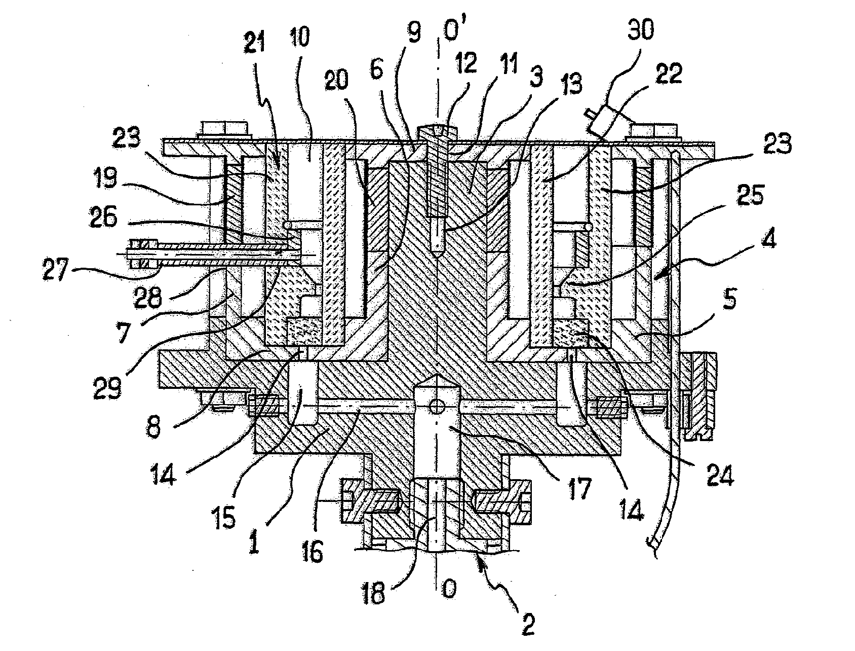
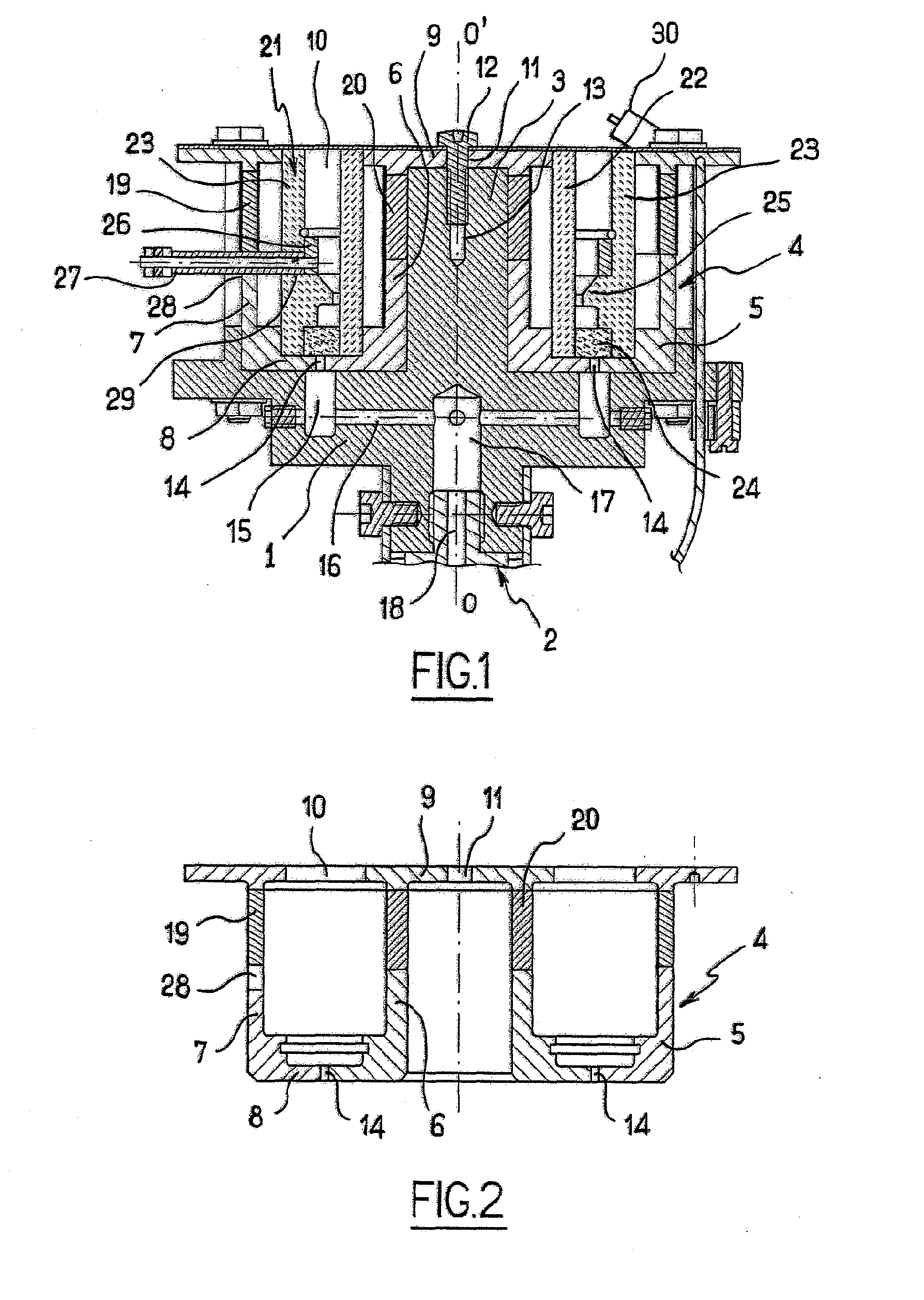
[0009]One of the objects of the invention is therefore to find a remedy for all these drawbacks by proposing an ion ejection device particularly suitable for making a plasma thruster of simple design, inexpensive and having low bulkiness. For this purpose and according to the invention, a
Hall effect ion ejection device is proposed, having a longitudinal axis substantially parallel to an ion ejection direction and including at least one main
ionization and acceleration annular channel, the annular channel being open at its end, an anode extending inside the channel, a
cathode extending outside the channel, at the outlet of the latter, and a magnetic circuit in order to generate a magnetic field in a portion of the annular channel into which a
noble gas is introduced, said circuit comprising at least one annular inner wall, one annular outer wall and a bottom connecting the inner and outer walls and forming the downstream portion of the magnetic field; said device is remarkable in that the magnetic circuit is laid out so as to generate at the outlet of the annular channel a magnetic field independent of
azimuth and, in the area of the anode, a magnetic field for which the radial component is zero.
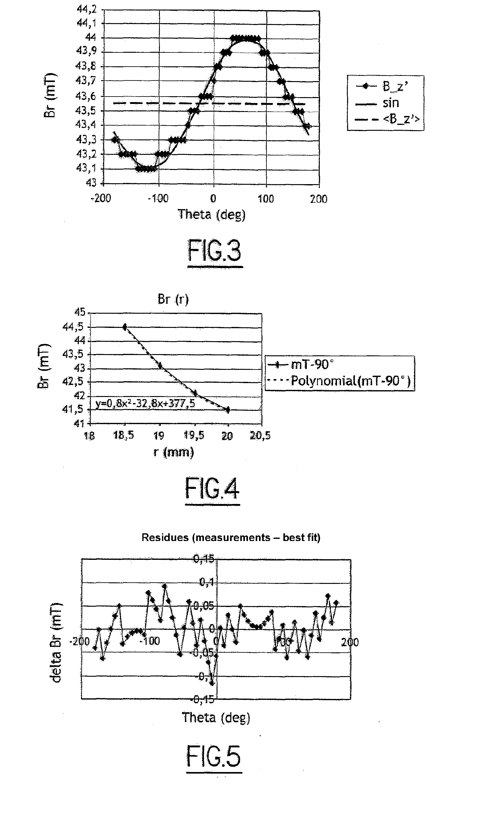
[0010]It will be noted that the fact that the magnetic field is independent of
azimuth, provides at the outlet of the annular channel a globally constant and quasi-radial magnetic field regardless of the azimuth. In this way, the electrons arriving in the outlet area of the annular channel with a velocity parallel to the axis of revolution of the device are subjected to a Laplace force which imparts a
cyclotron movement to them in the outlet plane of the annular channel. The electrons are thus massively trapped in the outlet area causing an increase in the probability of ionizing collisions with the atoms of the
noble gas. Further, the radial component of the magnetic field is zero in the area of the anode; the device does not require shielding in order to deform the field lines.
