Workpiece clamping device

Inactive Publication Date: 2010-09-16
SIEMENS AG
View PDF29 Cites 3 Cited by
  • Summary
  • Abstract
  • Description
  • Claims
  • Application Information

AI Technical Summary

Benefits of technology

[0008]It is an object of the present invention to create a workpiece clamping device of the type referred to in the introduction which is cost-effective to produce. In addition, by means of the workpiece clamping device according to the invention short clamping times and good accessibility of the workpiece during the machining are to be realized. Moreover, the workpiece clamping device is to be formed so that geometry deviations of the workpiece, especially of a turbine blade blank, have no significant influence upon the clamping situation. Also, the workpiece clamping device according to the present invention is to be formed in such a way that manufacturing errors on account of incorrectly clamped workpieces are minimized.
[0009]For achieving this object, or objects, the present invention creates a workpiece clamping device of the type referred to in the introduction, in which provision is made for at least one clamping strap for clamping the workpiece. Such a clamping strap is advantageous to the effect that very short clamping times can be realized. Also, geometry deviations of the workpiece which is to be machined remain on account of the flexibility of the clamping strap without significant influence upon the clamping situation. On account of the low overall height of the clamping strap, moreover, a very good accessibility of the workpiece in the clamped state is achieved. In addition, the use of a clamping strap instead of a conventional clamp ensures a better rigidity / weight ratio and facilitates the handling of the workpiece clamping device. A clamping strap, moreover, has a large support surface and a large angle of wrap on the workpiece and, depending upon the strap material which is used, can achieve good damping and can avoid vibrations during workpiece machining.
[0011]The at least one clamping strap can preferably be fixed on the basic body with capacity for adjustment in its clamping length. As a result of the variable clamping length, workpieces with a very wide variety of geometries can be clamped so that the workpiece clamping device according to the invention can be used in a very flexible manner.
[0017]The basic body can be preferably detachably mounted on different workpiece processing machines. Accordingly, a workpiece which is retained on the basic body can be transported in the clamped state from one workpiece processing machine to another. The workpiece correspondingly remains in the workpiece clamping device during different process steps so that reclamping of the workpiece can be entirely dispensed with. In this way, manufacturing errors on account of incorrectly clamped workpieces can be minimized.

Problems solved by technology

A disadvantage of this technique is that both the casting of the blade airfoil into the low melting alloy and also the removing of the alloy block after the machining of the blade airfoil are very complex which is why this method is very time-intensive and expensive.
In this case also, it is disadvantageous that the workpiece clamping device is constructionally complex and therefore expensive.
A significant disadvantage of this technique is that the workpiece clamping device is constructionally very complex and correspondingly expensive.

Method used


Image

  • Workpiece clamping device
  • Workpiece clamping device
  • Workpiece clamping device

Examples


Embodiment Construction

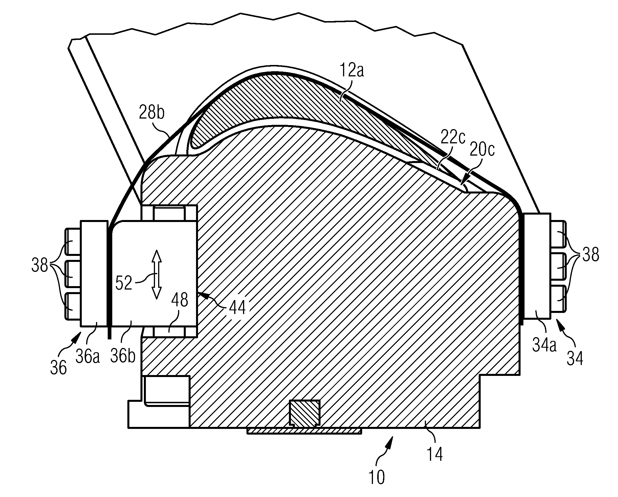
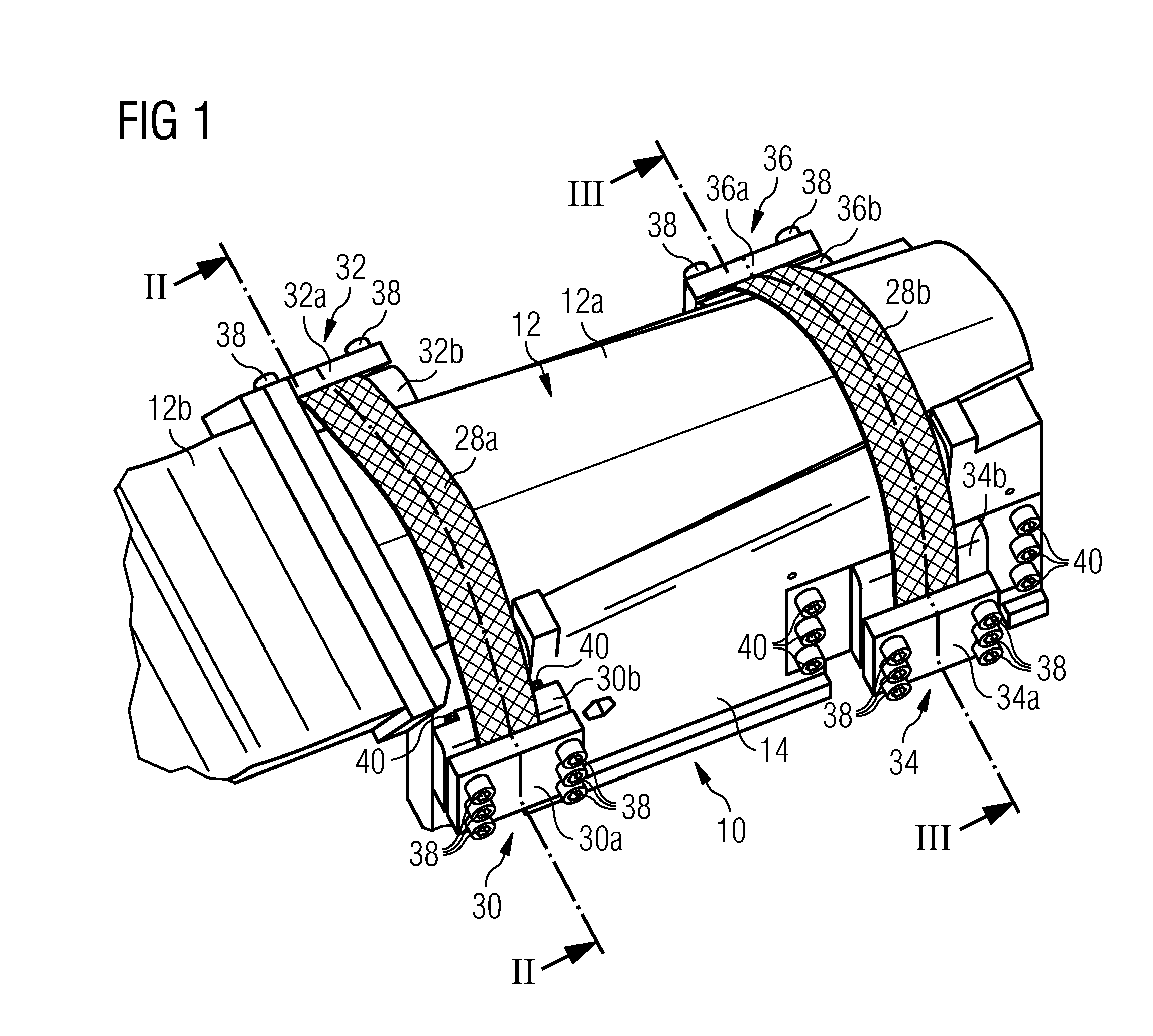
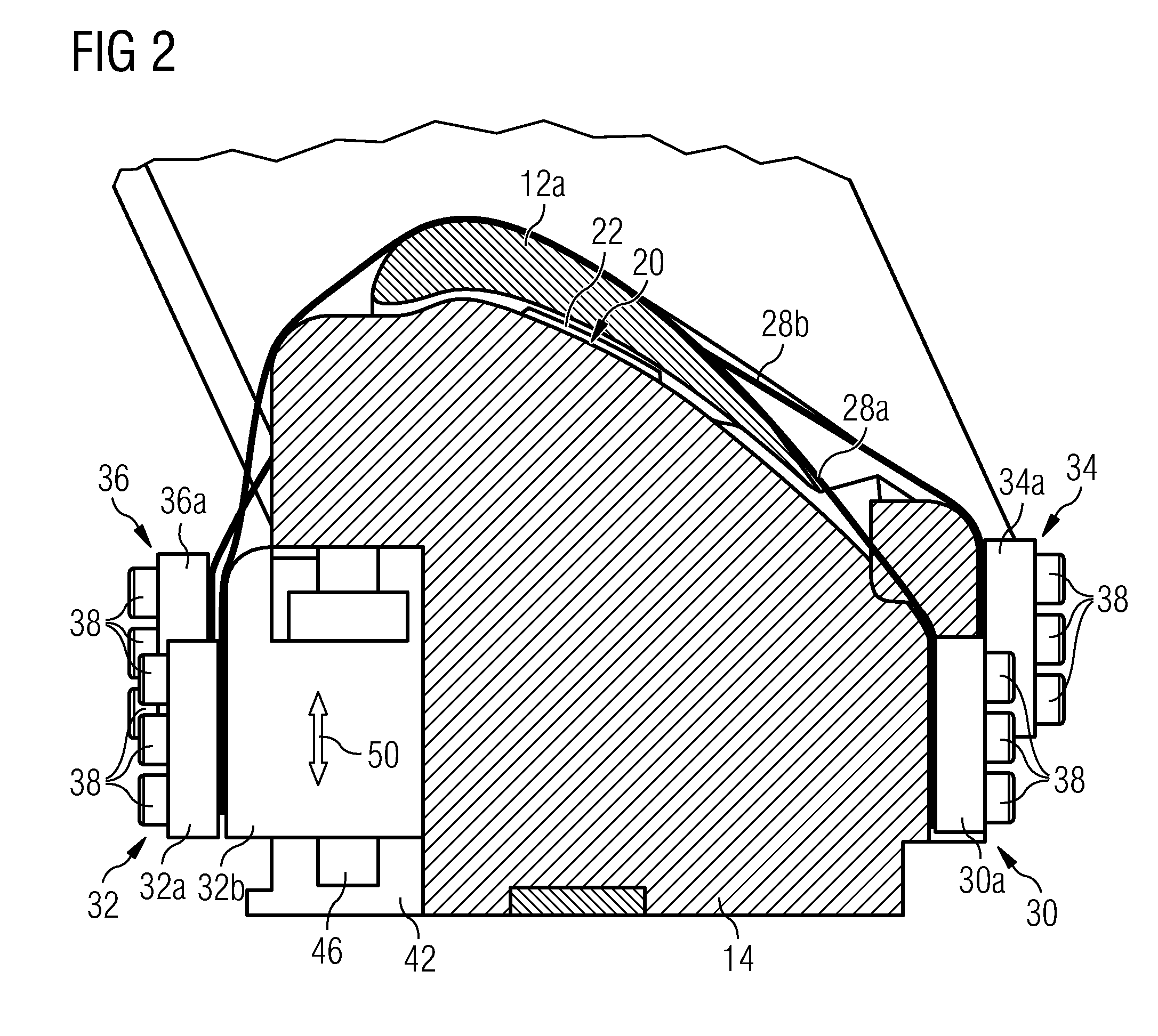
[0031]FIGS. 1 to 7 show a first embodiment of a workpiece clamping device 10 according to the invention, on which is clamped a workpiece in the form of a turbine blade 12 which has a blade airfoil 12a and a blade root 12b. The workpiece clamping device 10 comprises a basic body 14 consisting of metal, on the upper side of which a workpiece seat 16 for seating of the blade airfoil 12a of the turbine blade 12 is formed. The workpiece seat 16 comprises a base surface 18, the contour of which is essentially geometrically adapted to the outer contour of the underside of the blade airfoil 12a of the turbine blade 12. In addition, the workpiece seat 16 has three support elements 20 which project from the base surface 18, are geometrically adapted to the contour of the underside of the blade airfoil 12a, and in each case define a support surface 22 on which rests the underside of the blade airfoil 12a of the turbine blade 12. As a result of these support elements 20 a stable three-point bea...


PUM


Abstract

A workpiece clamping device for clamping a workpiece during machining is provided. The workpiece may be a turbine blade in the region of the blade airfoil. The workpiece clamping device includes a basic body with a workpiece seat, wherein provision is made for at least one clamping strap for clamping the workpiece.

Description

CROSS REFERENCE TO RELATED APPLICATIONS[0001]This application claims priority of European Patent Office application No. 09003634.4 EP filed Mar. 12, 2009, which is incorporated by reference herein in its entirety.FIELD OF INVENTION[0002]The present invention refers to a workpiece clamping device for clamping a workpiece during machining, especially a turbine blade clamping device for clamping a turbine blade in the region of the blade airfoil, which device has a basic body with a workpiece seat.BACKGROUND OF INVENTION[0003]The production of turbine blades is known in the prior art. For this, a blank of the turbine blade is cast in a first step. The blade airfoil of the blank is then fixed in a workpiece clamping device and the final geometry of the blade root is formed by material removal, for example by grinding, milling or the like.[0004]For the clamping of blade airfoils of a complicated shape various clamping techniques are used, such as casting into low melting alloys, hard cla...

Claims


Application Information

Patent Timeline
IPC IPC(8): B23Q3/00B25B1/20
CPCB23Q3/063B25B5/14B23Q3/069
Inventor FRIES, EDGARLISCHKA, JAN-MARKUHLMANN, ECKART
Owner SIEMENS AG
Why Eureka
Try Eureka