Automatic clamping platen device

An automatic clamping and pressing plate technology, which is applied in the direction of feeding devices, metal processing machinery parts, metal processing equipment, etc., can solve the problems of complex structure, high manufacturing cost, and few clamping points, and achieve simple structure and low manufacturing cost , The effect of short clamping time

Inactive Publication Date: 2009-10-14
ANYANG XINSHENG MACHINE TOOL
View PDF3 Cites 0 Cited by
  • Summary
  • Abstract
  • Description
  • Claims
  • Application Information

AI Technical Summary

Problems solved by technology

[0002] At present, the clamping and pressing plate devices used in various ordinary, CNC machine tools, special machine tools and component feeding devices in China are all mechanical clamping, with complex structures, large volume, few clamping points, and uneven force. Mechanical processing is prone to vibration, clamping and loosening, manual operation, and long changing time, which cannot realize the automation of machine tools and components, and the manufacturing cost is high; the requirements for automatic clamping, uniformity, firmness, simple structure, and small size of the pressing plate cannot be realized

Method used


Image

  • Automatic clamping platen device
  • Automatic clamping platen device
  • Automatic clamping platen device

Examples


Embodiment Construction

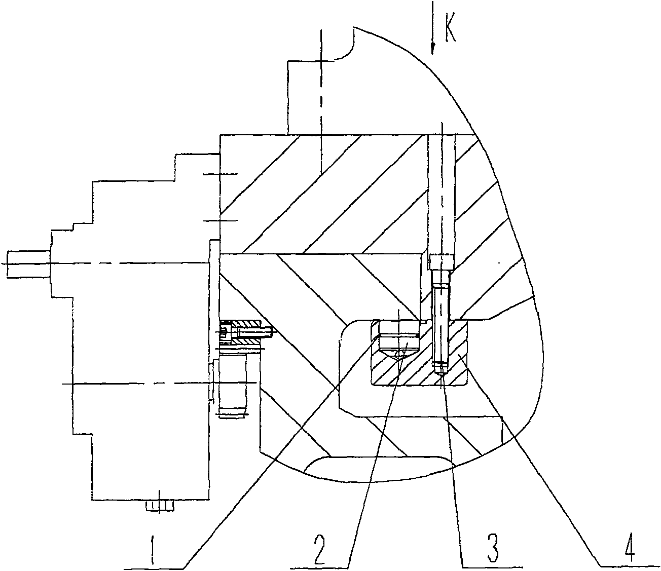
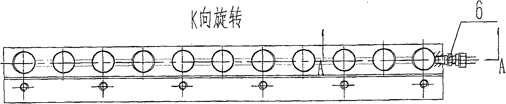
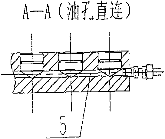
[0025] Such as figure 1 , 2 , 3, and 4, the present invention includes a pressing plate 4 fastened on the moving saddle by screws 3, each pressing plate body round hole distributed on the pressing plate 4 and the clamping piston 2 installed in the pressing plate body round hole form each One-way cylinder. The clamping piston 2 is sealed and connected with the circular holes of the pressing plate body distributed on the pressing plate 4 through the sealing ring 1 . The one-way oil cylinders are connected to each other through the oil passages 5 in the pressure plate body, and the oil passages 5 connected to each one-way oil cylinders are connected by oblique holes or straight holes between each one-way oil cylinders. A pipe joint 6 is installed at the end of the pressure plate 4, and the pipe joint 6 connects the external oil circuit with the oil channel 5 in the pressure plate 4 body. The hydraulic oil is controlled by electricity, enters the pressure plate body from the pi...


PUM


Abstract

The invention relates to an automatic clamping pressure pad device arranged on the feed apparatuses of various ordinary machine tool, numerical control machine, specific lathe and part used for the requirements of multiple station remaining, clamping and locating in a feeding process and meeting the automatic machining for various work-pieces and stations. The automatic clamping pressure pad device includes a pressure pad tightly fixed on a moving saddle by a bolt. The round holes for each pressure pad body arranged on the pressure pad and the pressure clamping pistons mounted in the round holes for each pressure pad body form each single direction oil cylinder. The automatic clamping pressure pad device with the advantages of simple structure, small size, uniform clamping pressure, good shake resistance and low manufacturing cost can clamp automatically and meet the requirements for multi-location pause and automatic clamping of various ordinary machine tool, numerical control machine, specific lathe and part during the feeding process.

Description

Technical field: [0001] The invention relates to a feeding device installed on various ordinary and numerically controlled machine tools, special machine tools and components, used for multi-station stop, clamping and positioning requirements during the feeding process, and meets the automatic processing requirements of different workpieces and stations Automatic clamping platen device. Background technique: [0002] At present, the clamping and pressing plate devices used in various ordinary, CNC machine tools, special machine tools and component feeding devices in China are all mechanical clamping, with complex structures, large volume, few clamping points, and uneven force. Mechanical processing is prone to vibration, clamping and loosening, manual operation, and long changing time, which cannot realize the automation of machine tools and components, and high manufacturing costs; the requirements for automatic clamping, uniformity, firmness, simple structure, and small si...

Claims


Application Information

Patent Timeline
Patent Type & Authority Patents(China)
IPC IPC(8): B23Q5/34
Inventor 韩长生郑文喜张安清侯剑峰李运生
Owner ANYANG XINSHENG MACHINE TOOL
Why Eureka
Try Eureka