
Grinding/polishing device for polygonal column member and grinding/polishing method

A grinding process, a grinding process technology, applied in the grinding/grinding device, grinding/grinding process field, can solve the problem of not having the known technology of the processing device disclosed, and achieve the effect of reliable grinding process

Active Publication Date: 2012-11-21
SINTOKOGIO LTD
View PDF10 Cites 16 Cited by
  • Summary
  • Abstract
  • Description
  • Claims
  • Application Information

AI Technical Summary

Problems solved by technology

[0019] In addition, in the above-mentioned prior art documents, there is no known technology that discloses a processing device having both functions of the above-mentioned grinding processing and grinding processing.

Method used


Image

  • Grinding/polishing device for polygonal column member and grinding/polishing method
  • Grinding/polishing device for polygonal column member and grinding/polishing method
  • Grinding/polishing device for polygonal column member and grinding/polishing method

Examples


Embodiment 1

[0135] Such as Figure 9 As shown, the silicon block (W) to be processed in the present embodiment 1 is obtained by cutting out one silicon ingot. When cutting out a silicon block from a silicon ingot, use a new wire saw with a fixed abrasive method to cut a square polycrystalline silicon block (W) consisting of four flat parts (F) and four corner parts (C) in a rectangular shape. Cut into 5 columns x 5 columns = 25 pieces in total. The silicon block (W) used in Example 1 is Figure 9 and Figure 10 The silicon block A cut out from the four corners of the silicon ingot is shown. In this silicon block A, protrusions are formed on two planar parts.

[0136] Table 1 and Table 2 show the contents of the initial setting items input to the control means (6) before the start of machining.

[0137] [Table 1]

[0138]

[0139] [Table 2]

[0140]

[0141]In the initial setting items shown in the above table 1, the interval size (100mm) of the reference plane of the reference...

Embodiment 2

[0163] The silicon block (W) to be processed in Example 2 is a single crystal silicon block (W) formed by cutting a cylindrical single crystal silicon ingot produced by the crystal pulling method. The upper and lower ends of the above-mentioned monocrystalline silicon ingot are cut off and removed, and the length (in Figure 11 , the direction perpendicular to the paper surface) is cut into the range of 299.0 ~ 301.0mm (called: 300mm), such as Figure 11 As shown, vertically fix 5 rows×5 rows=25 pieces in total to the fixing jig.

[0164] With respect to the above 25 single crystal silicon ingots, the outer peripheral portion of the main body of each single crystal silicon ingot was cut and removed by using the new fixed abrasive wire saw used in the above-mentioned Example 1. At this time, processing was performed so that four arc-shaped corners (C) having a width of about 25 mm were formed in a part of the outer periphery. Simultaneously cut and form four planar parts (F) ...


PUM

PropertyMeasurementUnit
depthaaaaaaaaaa
lengthaaaaaaaaaa
sizeaaaaaaaaaa

Abstract

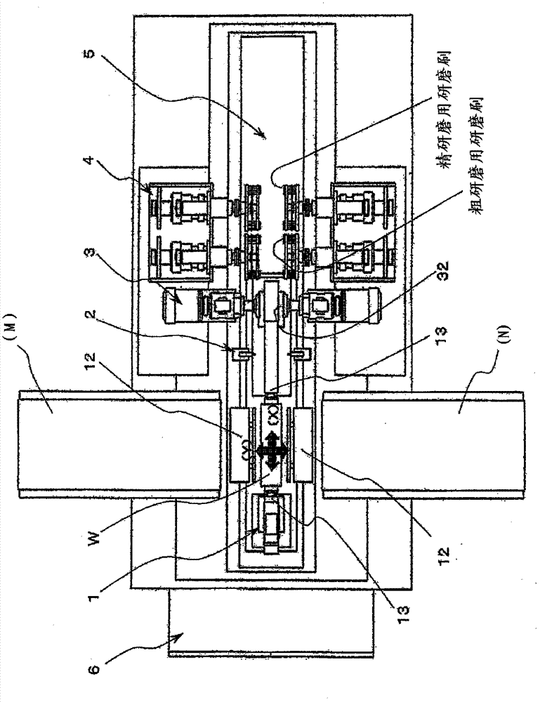
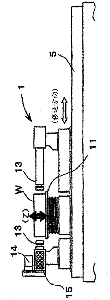
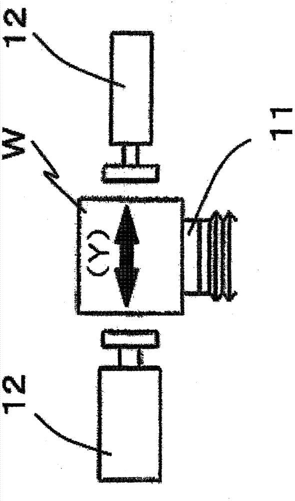
Provided are: a silicon block grinding / polishing device comprising a grinding function capable of grinding a square column-shaped silicon block within tolerance ranges of +-0.5 mm for the cross-section dimensions thereof and +-0.1 DEG for the perpendicular angles thereof, said block having been formed by cutting a silicon ingot using a wire saw, and comprising a polishing function capable of removing micro cracks in the surface layer of the cut silicon block (W); and a processing method therefor. The device comprises: a holding means (1) that holds the silicon block (W); a measuring means (2) that measures the cross-section dimensions of the silicon block (W); a grinding means (3) that grinds the planar sections (F) and the angular sections (C) of the silicon block (W); a polishing means (4) that polishes the planar sections (F) and the angular sections (C) of the silicon block (W) which has completed grinding and removes micro cracks; a transfer means (5) that transfers the holding means (1) holding the silicon block (W), between the measuring means (2), the grinding means (3), and the polishing means (4); and a control means (6) that operates each of the means.

Description

technical field [0001] The present invention relates to a grinding / grinding device and a grinding / grinding method for hard and brittle materials. Grinding device and grinding / grinding method. [0002] In addition, in the grinding process using the apparatus according to the present invention, the workpiece is finished into a cross-sectional shape having a predetermined specification size, and in the grinding process, microcracks ( micro crack). Background technique [0003] Examples of hard and brittle materials that are processed objects in the present invention include silicon blocks sliced ​​from silicon ingots in the process of manufacturing silicon wafers that are substrates of solar panels. There are two types of bulk silicon, polycrystalline and single crystal, which have different crystal structures. In the following, the grinding / grinding of polycrystalline and monocrystalline silicon blocks whose cross-sectional shape is quadrangular will be described as an exam...

Claims


Application Information

Patent Timeline
Patent Type & Authority Applications(China)
IPC IPC(8): B24B7/16B24B7/22B24B9/00B24B29/00B24D13/14
CPCB24B7/22B24B7/16B24B51/00B24B9/00B24B29/00B24B29/005B24B49/00B24D13/14
Inventor 棚桥茂平野雅雄泽井将太
Owner SINTOKOGIO LTD
Learn More