Long-stroke quick clamping mechanism

A clamping mechanism and large stroke technology, applied in workpiece clamping devices, manufacturing tools, etc., can solve the problems of long clamping time and low clamping efficiency, and achieve short clamping time and high clamping efficiency. Effect

Inactive Publication Date: 2011-02-16
WUXI YELONG PRECISION MACHINERY
View PDF0 Cites 0 Cited by
  • Summary
  • Abstract
  • Description
  • Claims
  • Application Information

AI Technical Summary

Problems solved by technology

When these screw clamping mechanisms work, they need to rotate more handle turns, the clamping time is longer, and the clamping work efficiency is low.

Method used


Image

  • Long-stroke quick clamping mechanism
  • Long-stroke quick clamping mechanism
  • Long-stroke quick clamping mechanism

Examples


Embodiment Construction

[0010] The present invention will be further described below in conjunction with specific drawings and embodiments.

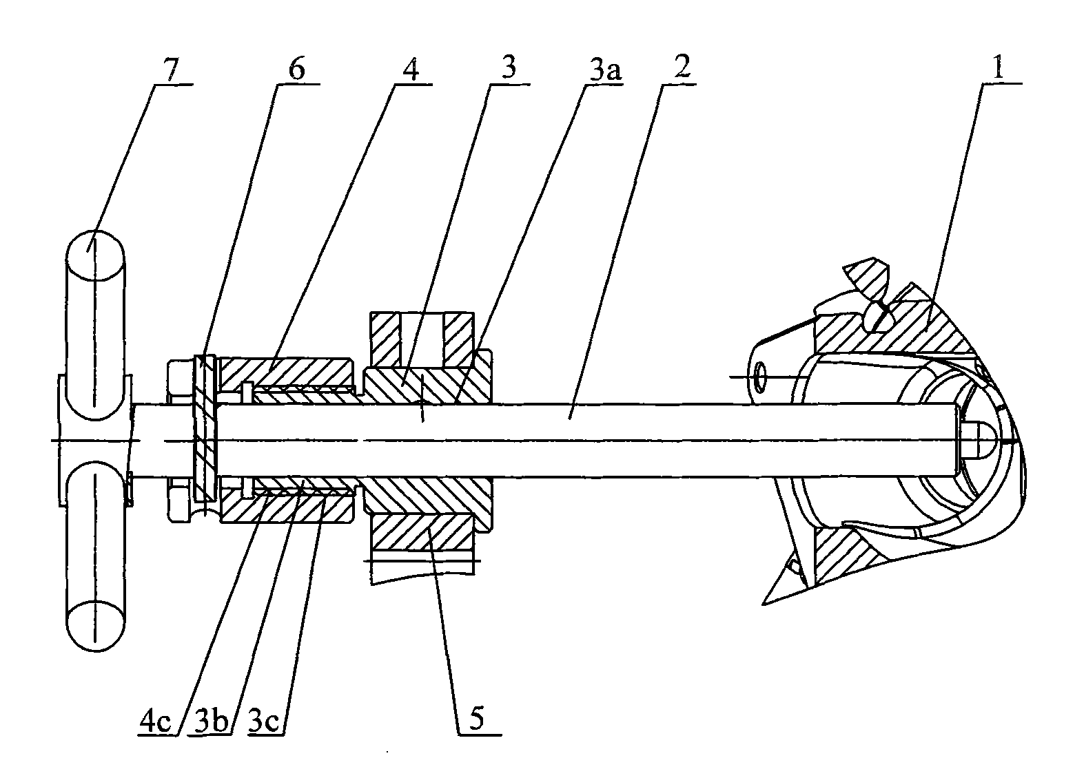
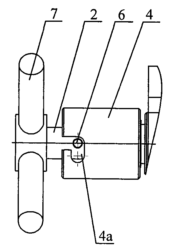
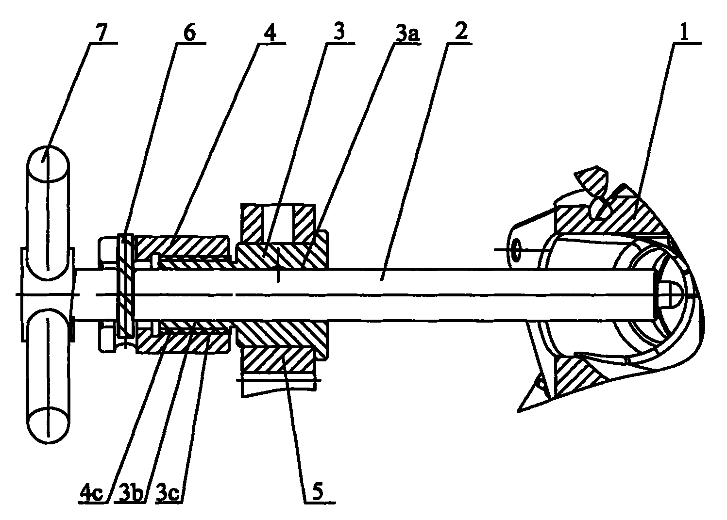
[0011] As shown in the figure: the large-stroke quick clamping mechanism includes a guide sleeve 3 fixedly installed on the base 5, a guide hole 3a is opened in the guide sleeve 3, and a guide hole 3a is provided on the side wall of the guide sleeve 3 to be integrally connected with it. The tubular body 3b is provided with a first thread 3c on the outer surface of the tubular body 3b or the inner hole wall of the tubular body 3b, and also has a nut sleeve 4, the outer surface of the nut sleeve 4 or the inner hole of the nut sleeve 4 The wall is provided with a second thread 4c that engages with the first thread 3c. The inner hole of the nut sleeve 4, the inner hole of the tubular body 3b, and the guide hole 3a are concentric, and a push rod 2 is inserted through the nut sleeve 4 in turn. The inner hole, the inner hole of the tubular body 3b and the guide hole 3...


PUM


Abstract

The invention relates to a long-stroke quick clamping mechanism for clamping workpieces. According to the technical proposal provided by the invention, the long-stroke quick clamping mechanism comprises a guide sleeve fixedly arranged on a base and a nut sleeve; the guide sleeve is internally provided with a guide hole; the side wall of the guide sleeve is provided with a tubular body which is integrally connected with the guide sleeve around the guide hole; the outer surface of the tubular body or an inner hole wall body of the tubular body is provided with first threads; the outer surface ofthe nut sleeve or an inner hole wall body of the nut sleeve is provided with second threads which are engaged with the first threads; an inner hole of the nut sleeve, an inner hole of the tubular body and the guide hole are concentric; a post rod is inserted and sequentially passes through the inner hole of the nut sleeve, the inner hole and the guide hole; and a locking device is arranged between the post rod and the sleeve nut. When the long-stroke quick clamping mechanism works, the clamping can be achieved by only needing to rotate a handle for fewer circles; and the long-stroke quick clamping mechanism has the advantages of short clamping time, high clamping working efficiency and the like.

Description

technical field [0001] The invention relates to a large-stroke fast clamping mechanism for clamping workpieces. Background technique [0002] The screw clamping mechanism is the most commonly used fixture clamping mechanism. The existing commonly used screw clamping mechanisms have the following types: 1. Use bolts to compress through briquetting blocks; 2. Compose a composite mechanism with various pressing plates. When these screw clamping mechanisms work, it is necessary to rotate more handle turns, the clamping time is longer, and the clamping work efficiency is lower. Contents of the invention [0003] The purpose of the present invention is to overcome the deficiencies in the prior art, and to provide a fast clamping mechanism with a large stroke that requires fewer turns of the handle to achieve clamping, a shorter clamping time, and higher clamping efficiency. . [0004] According to the technical solution provided by the present invention, the large-stroke quick...

Claims


Application Information

Patent Timeline
Patent Type & Authority Patents(China)
IPC IPC(8): B25B11/00
Inventor 吴军
Owner WUXI YELONG PRECISION MACHINERY
Why Eureka
Try Eureka