Optical-fiber-characteristic measuring device and optical-fiber-characteristic measuring method
a measuring device and optical fiber technology, applied in the direction of optical apparatus testing, instruments, structural/machine measurement, etc., can solve the problems of insufficient application method and long time, and achieve the effect of improving the intensity of output light, and extending the measurement rang
- Summary
- Abstract
- Description
- Claims
- Application Information
AI Technical Summary
Benefits of technology
Problems solved by technology
Method used
Image
Examples
first embodiment
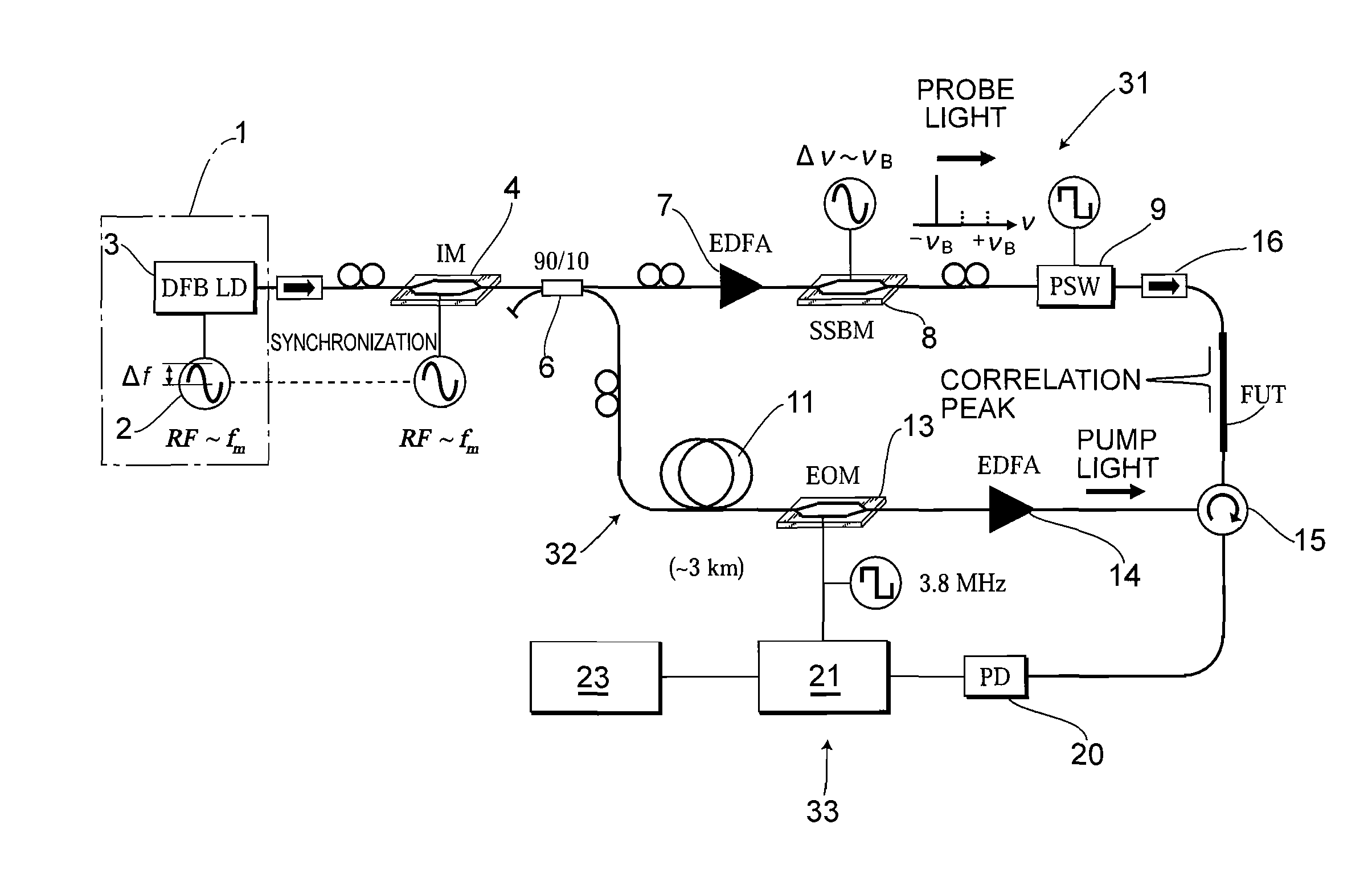
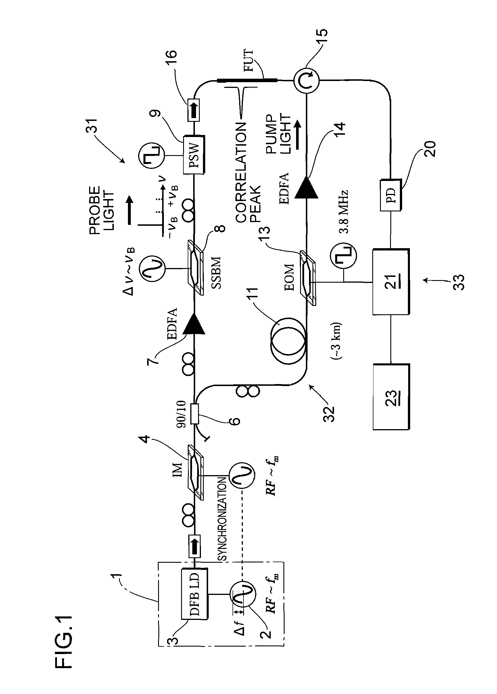
[0031]FIG. 1 shows an optical-fiber-characteristic measuring apparatus according to the In the figure, reference numeral 1 denotes a light source which comprises a signal generator 2 and a semiconductor laser 3. A possible semiconductor laser 3 is, for example, a distributed feedback laser diode (DFB LD) which is small in size and emits a laser light having a narrow spectrum width. The signal generator 2 is for outputting a desired modulated signal as an injected current to the semiconductor laser 3 to perform sinusoidal frequency modulation (including phase modulation) on continuous laser light emitted from the semiconductor laser 3.
[0032]Reference numeral 4 denotes an optical intensity modulator (IM) as intensity modulating means for performing intensity modulation on output light from the semiconductor laser 3 in synchronization with the frequency modulation performed on the semiconductor laser 3. The optical intensity modulator 4 has a function of receiving a synchronization si...
second embodiment
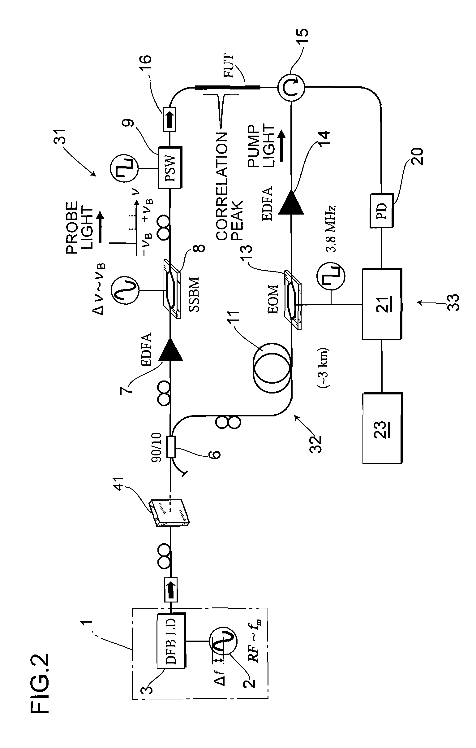
[0069]FIG. 2 shows an apparatus and an optical filter 41 having an appropriate transmission spectrum characteristic is disposed in the optical path of the output light from the light source 1 instead of the optical intensity modulator 4. In this case, the optical filter 41 substantially performs intensity modulation as the intensity modulating means in synchronization with the frequency modulation performed on the output light from the light source 1, thereby appropriately adjusting the spectrum distribution of the output light. In a case where the optical filter 41 is used, the output light can be intensively adjusted in accordance with the frequency thereof because of the filtering characteristic of the optical filter 41, the synchronization signal from the signal generator 2 becomes unnecessary, and the reduction of the noise S2 and the extension of the measurement range dm remarkably easily achieved.
third embodiment
[0070]Further, as another structure of the intensity modulating means, a direct-modulation-scheme type signal generator 51 which performs frequency modulation on the output light from the light source 1 with repeated waveforms other than a sinusoidal wave instead of the external-modulation-scheme type optical intensity modulator 4. FIG. 3 shows such an example as a third embodiment, and the signal generator 51 has a function of performing frequency modulation on the output light from the semiconductor laser 3 with a triangular repeated waveform for example.
[0071]FIG. 14 shows frequency modulation waveforms for a case where the output light is subjected to frequency modulation with a conventional sinusoidal repeated waveform, and for a case where the output light is subjected to frequency modulation with a repeated waveform other than the sinusoidal waveform, and time-average spectrum shapes calculated from those frequency modulation waveforms. In the figure, the upper part of (a) sh...
PUM
| Property | Measurement | Unit |
|---|---|---|
| frequency modulation | aaaaa | aaaaa |
| frequency | aaaaa | aaaaa |
| frequency shift | aaaaa | aaaaa |
Abstract
Description
Claims
Application Information
 - R&D
- Intellectual Property
- Life Sciences
- Materials
- Tech Scout
- Unparalleled Data Quality
- Higher Quality Content
- 60% Fewer Hallucinations
Browse by: Latest US Patents, China's latest patents, Technical Efficacy Thesaurus, Application Domain, Technology Topic, Popular Technical Reports.
© 2025 PatSnap. All rights reserved.Legal|Privacy policy|Modern Slavery Act Transparency Statement|Sitemap|About US| Contact US: help@patsnap.com


