
Method for manufacturing a shaft member having a sintered part bonded thereto and a camshaft for an internal combustion engine

a technology of internal combustion engine and shaft member, which is applied in the direction of machines/engines, valve drives, gearing, etc., can solve the problems of reducing the strength, the degree of freedom may be decreased, and the strength may be affected, so as to reduce the strength, increase the process yield and degree of freedom in design, the effect of reducing costs

Inactive Publication Date: 2010-09-09
NIPPON PISTONRING CO LTD
View PDF13 Cites 19 Cited by
  • Summary
  • Abstract
  • Description
  • Claims
  • Application Information

AI Technical Summary

Benefits of technology

[0008]Also in the method disclosed in the above-mentioned Patent Document 3, the recess is required to be formed in the same manner as the above-mentioned Patent Document 1, thus causing problems on decrease in degree of freedom in design and strength. Further, in addition to the cam lobe and shaft, the pin is required to be used, thus complicating the manufacturing process, decreasing process yield and increasing the manufacturing costs.
[0010]A primary object of the present invention, which was made to solve the above-mentioned problems, is to provide a method for manufacturing a shaft member having a sintered part bonded thereto, which method is simple and provides an increased process yield and a high accuracy in position and angle of the sintered part, as well as a cam shaft for an internal combustion engine, manufactured by the above-mentioned method.Means to Solve the Subject
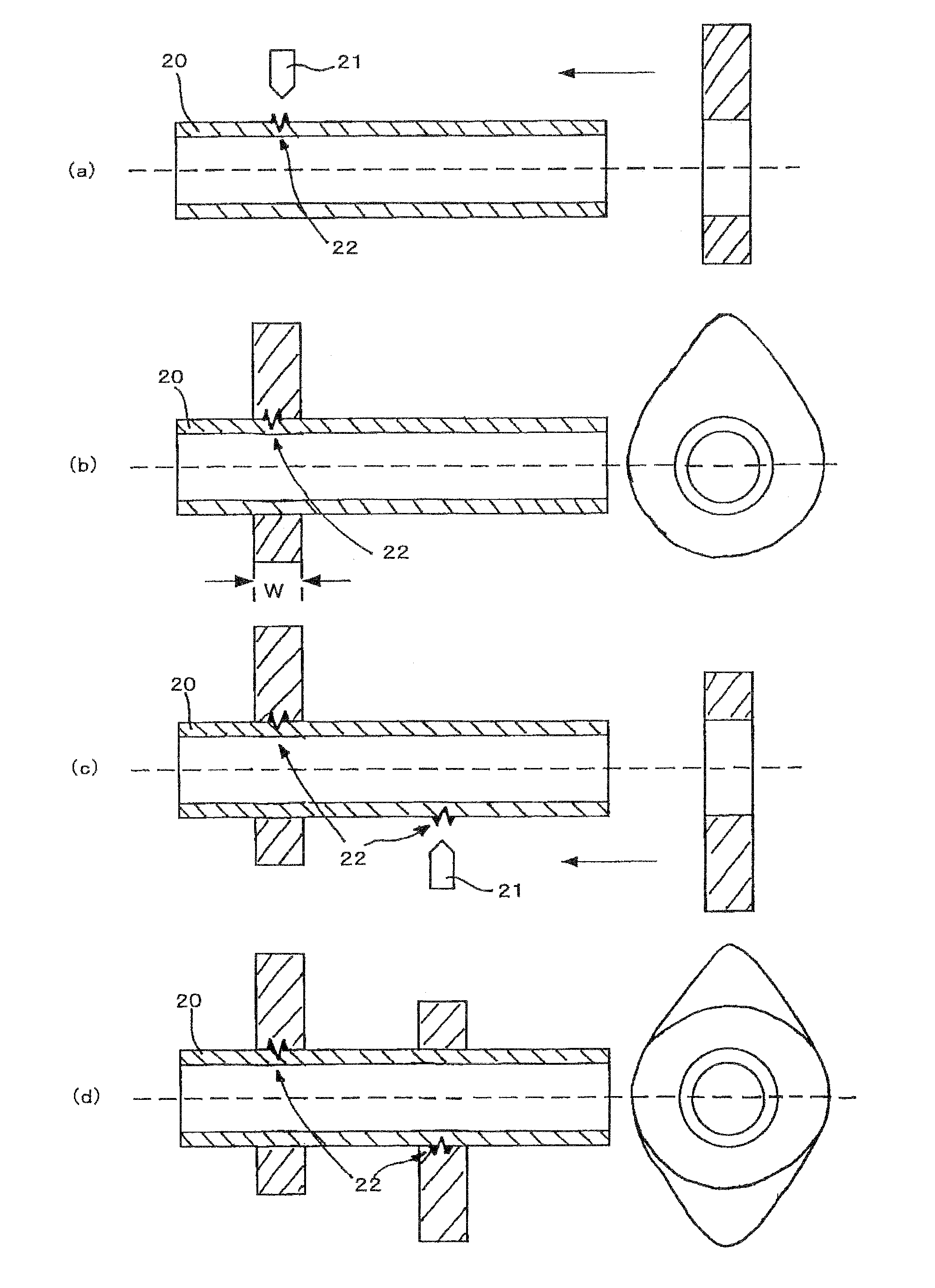
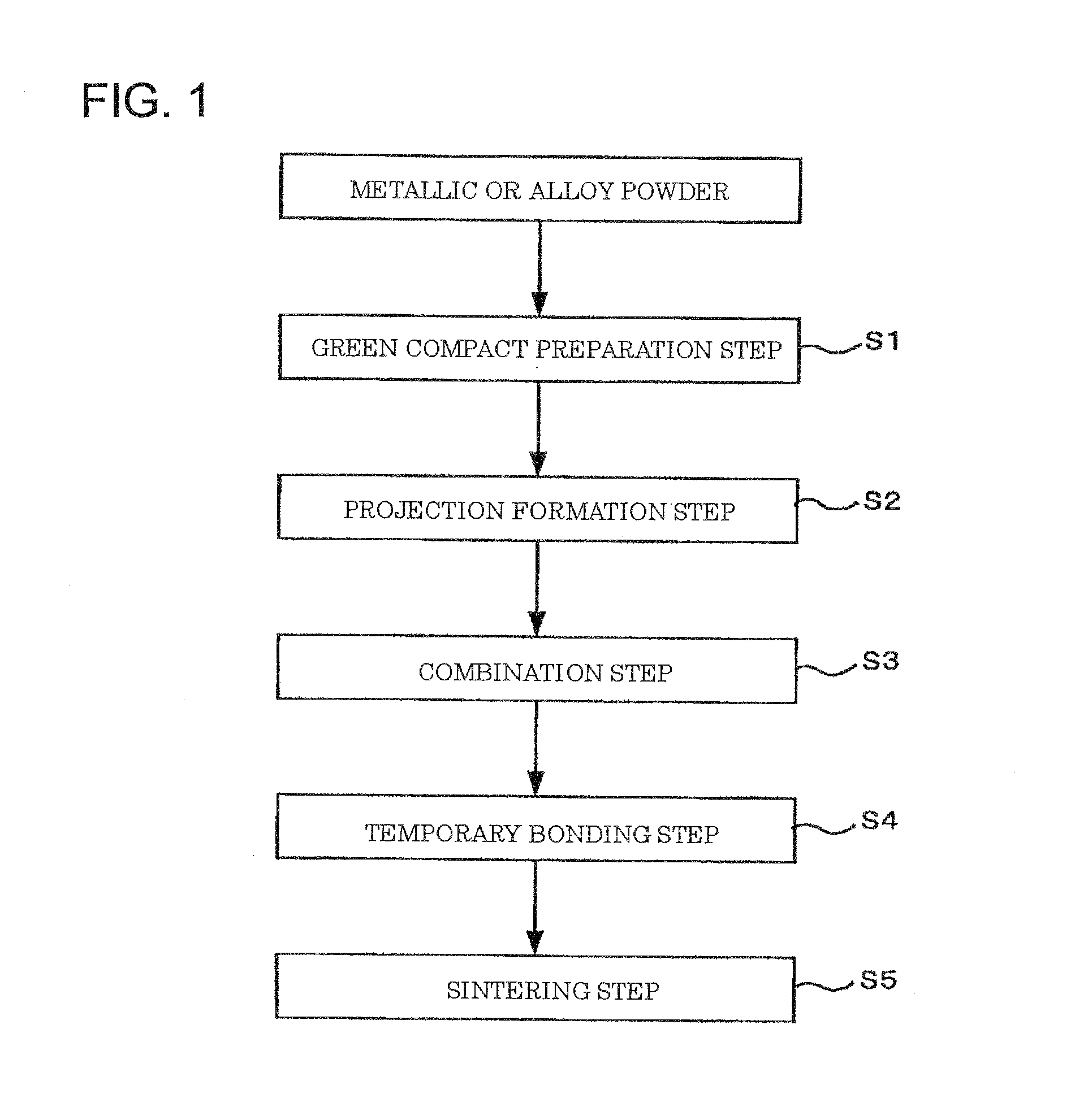
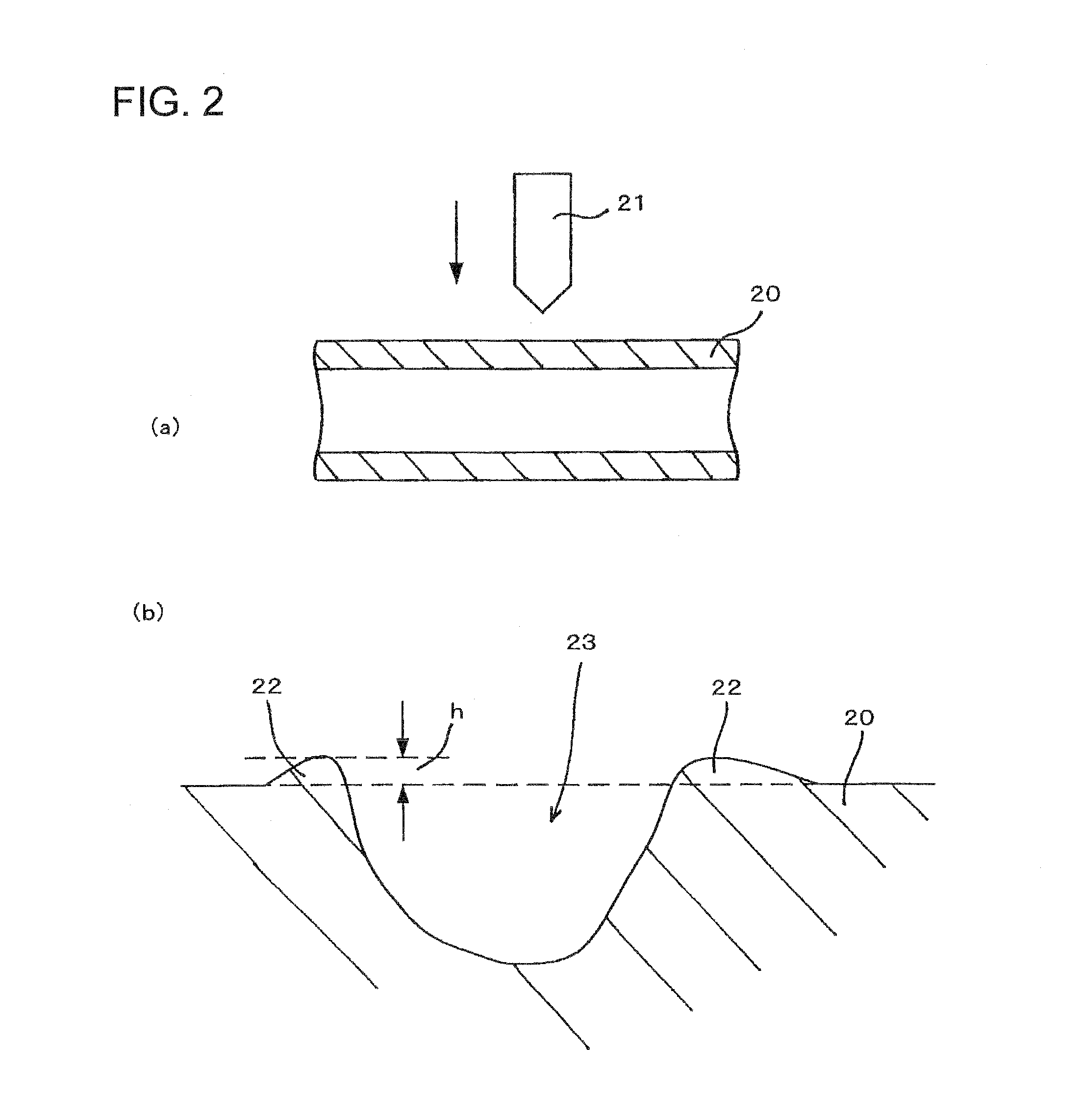
[0015]According to the present invention, in the method for manufacturing a shaft member having a sintered part bonded thereto, wherein a green compact made of a metal or alloy powder is placed on a shaft member and then sintered to prepare an integral body through a sinter-diffusion bonding, a fine projection is formed on the surface of the shaft member before placing the green compact on the shaft member, so that such a projection is utilized to ensure a stationarily combined state of the green compact and the shaft member. Therefore, there is no need to apply, in the same manner as the above-mentioned Patent Documents 1 and 2, a working step to both of the green compact (the cam lobe in Patent Documents 1 and 2) and the shaft member (the shaft in Patent Documents 1 and 2), and applying a working step only to the shaft member suffices, this making it possible to increase process yield and degree of freedom in design. In addition, the working step to be applied to the shaft member in the manufacturing method of the present invention is only to pressing a pressing device onto the surface of the shaft member to form a fine projection, and the projection is embedded eventually into the green compact at the contact portion therewith, with the result that such a working step does not decrease the strength unlike the above-mentioned Patent Documents 1 and 2.
[0017]In the manufacturing method of the present invention, the fine projection formed on the outer peripheral surface of the shaft member is embedded into the green compact, so as to ensure a stationarily combined state of the shaft member and the green compact. It is therefore possible to prevent the cam lobe from shifting unfavorably in the axial direction or rotating in a manner as described in Patent Document 4, thus improving accuracy in position and angle of the sintered part.

Problems solved by technology

However, in the method disclosed in the above-mentioned Patent Document 1 and Patent Document 2, the projection and recess, which are required to be formed, are not essential to the camshaft in its primary functions, with the result that degree of freedom in design may be decreased.
In case where the recesses (i.e., the grooves) are continuously formed on the outer peripheral surface of the shaft in its axial direction, a gap may be formed between the cam lobe and the portion of the shaft, on which the recesses are formed, thus causing problems in strength.
Also in the method disclosed in the above-mentioned Patent Document 3, the recess is required to be formed in the same manner as the above-mentioned Patent Document 1, thus causing problems on decrease in degree of freedom in design and strength.
Further, in addition to the cam lobe and shaft, the pin is required to be used, thus complicating the manufacturing process, decreasing process yield and increasing the manufacturing costs.

Method used


Image

  • Method for manufacturing a shaft member having a sintered part bonded thereto and a camshaft for an internal combustion engine
  • Method for manufacturing a shaft member having a sintered part bonded thereto and a camshaft for an internal combustion engine
  • Method for manufacturing a shaft member having a sintered part bonded thereto and a camshaft for an internal combustion engine

Examples


example 1

Conventional Example 1

[0069]The camshafts (each shaft having a single cam lobe) were prepared in accordance with the conventionally known method for manufacturing an assembled camshaft. These camshafts will be hereinafter referred to as “Sample Nos. 13 to 15”, respectively.

[0070]The same conditions of the alloy powder and the shaft as the above-mentioned example were applied.

[0071]The conventionally known method for manufacturing an assembled camshaft comprised the steps of forming a groove extending along the axial direction of a shaft on the outer peripheral surface thereof, forming a projection on an inner peripheral surface of a green compact for a cam lobe, which was to be fitted onto the shaft, fitting the green compact for the cam lobe onto the shaft so as to fit the projection into the groove, and sintering them to bond the cam lobe to the shaft (see FIGS. 1 to 3 of Patent Document 2 as mentioned above).

[0072]Evaluation was made in the same manner as Example 1 as described a...


PUM

PropertyMeasurementUnit
Lengthaaaaaaaaaa
Lengthaaaaaaaaaa
Angleaaaaaaaaaa

Abstract

A method for manufacturing a shaft member having a sintered part bonded thereto is simple and provides an increased process yield and a high accuracy in position and angle of the sintered part. A green compact is prepared by subjecting a metal or alloy powder to a compression molding. A projection formed on an outer peripheral surface of the shaft member is embedded into the green compact, while chipping partially the green compact with the projection, to combine the green compact with the shaft member. Then, a sintering is carried out.

Description

TECHNICAL FIELD[0001]The present invention relates to a method for manufacturing a shaft member having a sintered part bonded thereto. More specifically, the present invention relates to a manufacturing method, which is applicable to manufacture of for example a so-called “assembled camshaft”.BACKGROUND OF THE INVENTION[0002]A camshaft used for an internal combustion engine such as, for example, an automobile engine has been manufactured by compression-molding a metal or alloy powder into a cam lobe shape, placing same onto a shaft serving as a shaft member, and then sintering them to bond the sintered cam lobe integrally to the shaft through a sinter-diffusion bonding.[0003]In such a method for manufacturing a so-called “assembled camshaft”, there is a need to carry out a sintering step, while stationarily placing the sintered cam lobe in a predetermined position and at a predetermined angle on the shaft serving as the shaft member. Various methods of stationarily placing the cam l...

Claims


Application Information

Patent Timeline
IPC IPC(8): F01L1/047B22F7/02
CPCB22F7/062B22F7/08B22F2998/10B23P11/00B23P2700/02F16H53/025B22F3/02B22F3/164B22F3/10F16C3/02F16H3/02B22F7/06
Inventor KUWAHARA, TAKESHIAOKI, ATSUYASHINZAWA, MASAHIROTAKIGUCHI, HIROSHI
Owner NIPPON PISTONRING CO LTD
Learn More