
Laser oscillator and laser beam oscillation method

a laser beam and laser beam technology, applied in laser details, electrical equipment, active medium materials, etc., can solve the problems of large cost, long time required for manufacture, and unstable oscillation

Inactive Publication Date: 2010-08-26
TOKAI UNIV
View PDF4 Cites 7 Cited by
  • Summary
  • Abstract
  • Description
  • Claims
  • Application Information

AI Technical Summary

Benefits of technology

[0007]The present invention provides a laser oscillator and a method of oscillating a laser beam in which a segregation into local modes of transverse mode patterns is suppressed and a single frequency oscillation is achieved in a TEM00 mode using a ceramic laser medium having a material such as Nd:YAG ceramics or Yb:YAG ceramics.
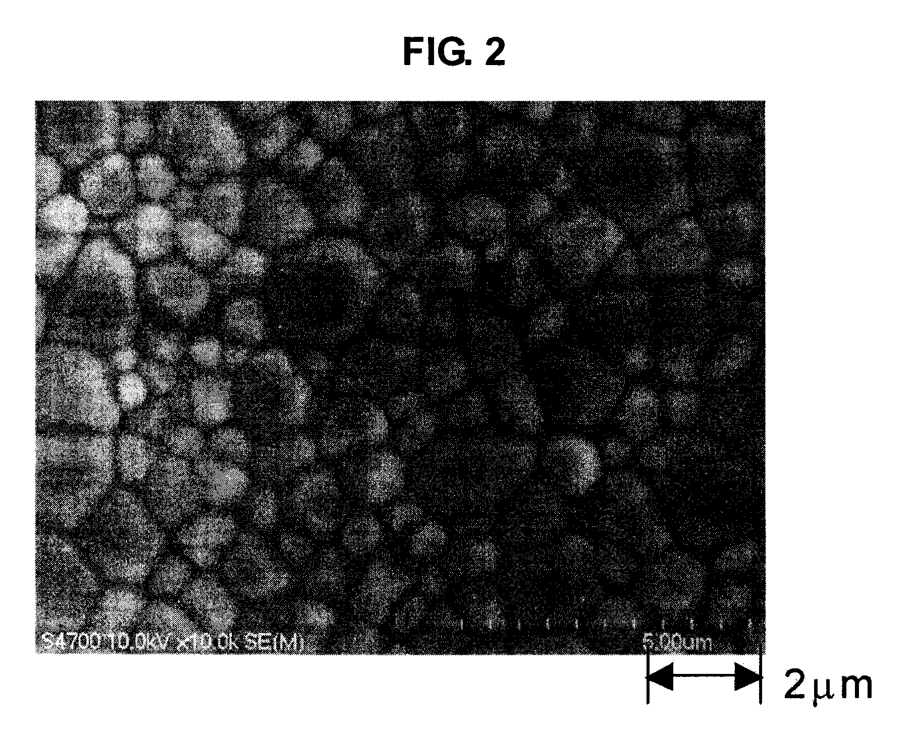
[0008]The present application discloses a laser oscillator having a laser light source which emits a pumping light, and a laser medium having a Nd:YAG ceramic or a Yb:YAG ceramic with an average grain size of 5 μm or less and into which the pumping light is irradiated.
[0009]According to the present invention, a laser oscillator and a method of oscillating a laser beam are provided in which a segregation into local modes of transverse mode patterns is suppressed and a single frequency oscillation is achieved in a TEMoo mode using a ceramic laser medium.

Problems solved by technology

However, it is difficult to obtain a product with a high concentration of additives due to manufacturing limitations and it is difficult to obtain a large single crystal so that large costs and a long time are required for manufacture.
Also, it is known that when this type of segregation occurs, an intensity modulation at beat frequencies among local modes appears due to the coupling of electrical fields of spatially adjacent local modes and the oscillation becomes unstable (for example, refer to T. Narita, Y. Miyasaka, and K. Otsuka, Jpn. J. Appl. Phys.

Method used


Image

  • Laser oscillator and laser beam oscillation method
  • Laser oscillator and laser beam oscillation method
  • Laser oscillator and laser beam oscillation method

Examples


first embodiment

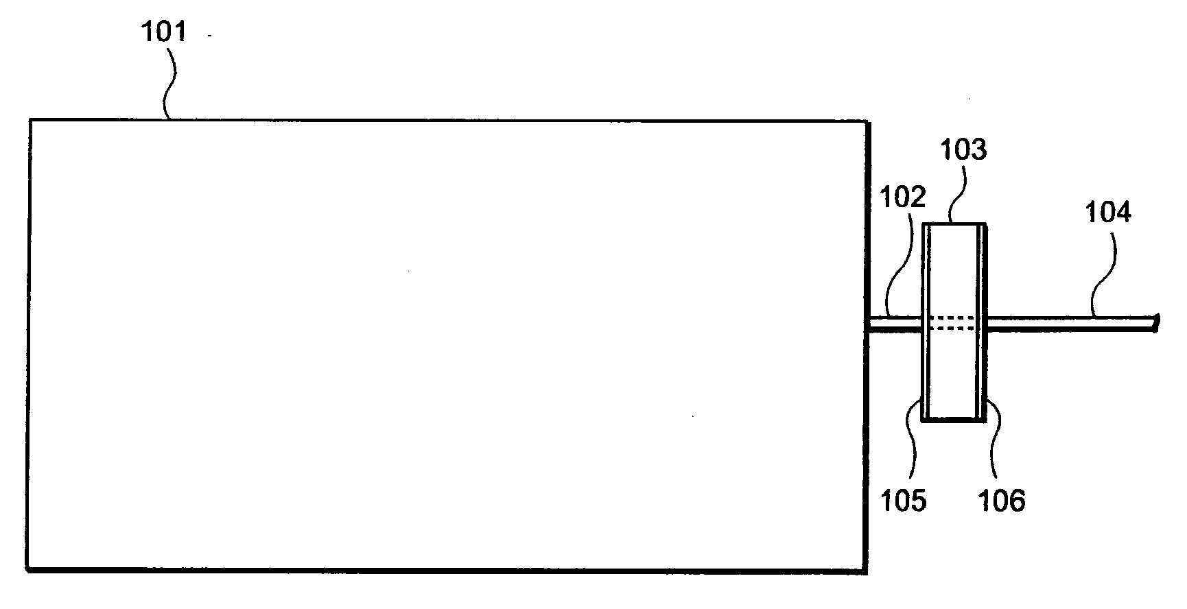
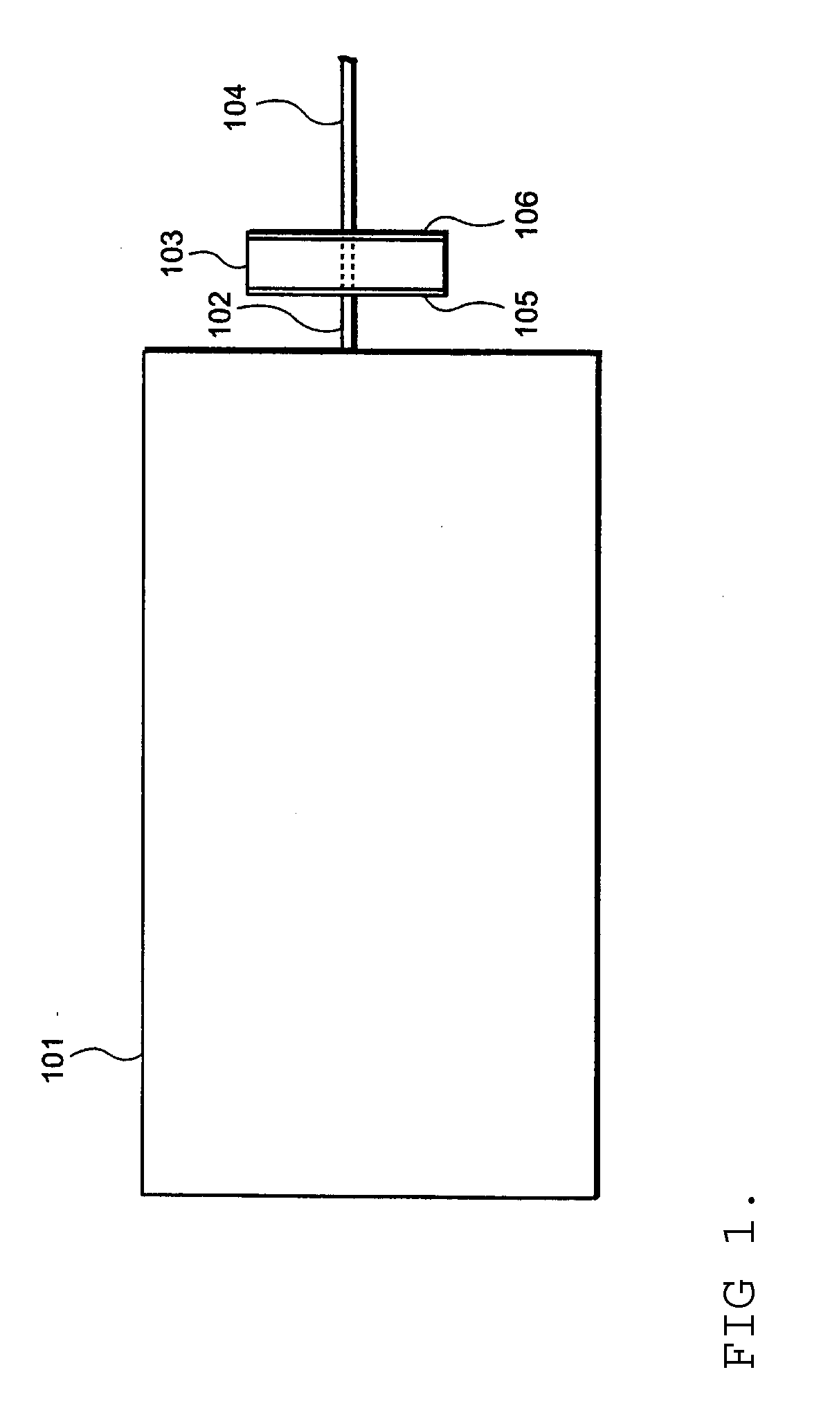
[0033]FIG. 1 shows a functional block diagram of a laser oscillator related to the first embodiment of the present invention. The laser oscillator related to the first embodiment of the present invention includes a laser light source 101 and a laser medium 103.

[0034]The laser light source 101 emits a pumping light 102. In the present embodiment, though a laser light source using a semiconductor is used for the pumping light source, a gas laser (for example, an Ar laser or a Kr laser) or a solid-state laser (for example a Ti sapphire laser) may also be used. In the case of using a Nd:YAG ceramic as a material of the laser medium 103, which is explained below, the wavelength of the pumping light 102 is 808 nm or 885 nm for example.

[0035]The laser medium 103 is a laser medium which is irradiated with the pumping light 102. In the present embodiment, a Nd: YAG ceramic with an average grain size of 5 μm or less is used as a laser medium. In the present embodiment, the laser medium 103 fo...

second embodiment

[0054]Next, a laser oscillator in which the segregation into local modes of transverse mode patterns is suppressed and an oscillation of a single frequency is achieved in a TEM00 mode by using a Yb:YAG ceramic material is explained. The inventor of the present invention, who has examined the measurement results of the characteristics of a laser beam obtained by the laser oscillator related to the first embodiment of the present invention, has predicted that there would be no segregation into local modes and that the stable operation would be possible even with a laser oscillator of a different material using a micro-grained ceramic which has an average grain size of 5 μm or less, and has invented a laser oscillator related to the second embodiment of the present invention.

[0055]FIG. 11 shows a functional block diagram of a laser oscillator related to the second embodiment of the present invention. The laser oscillator related to the second embodiment of the present invention include...

third embodiment

[0067]In the first and second embodiments explained hereto, while the ceramics used are different: Nd:YAG is used in one embodiment and Yb:YAG is used in another embodiment, the beam diameters of the pumping lights between the first and second embodiments are also different. Then, the third embodiment of the present invention is explained in order to confirm that that pumping beam diameter dependency of the transverse mode properties does not exist. When the pumping beam diameter is increased, a gain region in a radial direction becomes larger and a pumping beam diameter increases. In this case, while a threshold pumping power increases because an oscillation mode volume increases, because the pumping beam diameter can be increased compared to an average grain size, a laser beam is generated under the following conditions in order to examine (1) whether the formation of a local mode is decided by the ratio of average grain size and pumping beam diameter (a relative value) or (2) whe...


PUM


Abstract

By using a ceramics laser medium such as Nd:YAG ceramics or Yb:YAG ceramics, division of a lateral mode pattern to a local mode is suppressed so that single frequency, linear polarization oscillation are achieved in TEM00 mode. A laser oscillator comprising a laser light source for oscillating the pumping light, and a laser medium of Nd:YAG ceramics or Yb:YAG ceramics having an average grain size of 5 μm or less upon which the pumping light impinges is provided. The laser medium may have a first surface having a first dielectric multilayer film, and a second surface having a second dielectric multilayer film.

Description

CROSS REFERENCE TO RELATED APPLICATIONS[0001]This application is based upon and claims the benefit of priority from the prior Japanese Patent Application No. 2007-218019, filed on Aug. 24, 2007, and PCT Application No. PCT / JP2008 / 064755, filed on Aug. 19, 2008, the entire contents of which are incorporated herein by reference.BACKGROUND OF THE INVENTION[0002]1. Technical Field[0003]The present invention is related to a laser oscillator and a method of oscillating a laser beam.[0004]2. Description of the Related Art[0005]Conventionally, a single crystal such as Nd:YAG is known as a material of a solid-state laser medium. However, it is difficult to obtain a product with a high concentration of additives due to manufacturing limitations and it is difficult to obtain a large single crystal so that large costs and a long time are required for manufacture. On the other hand, a laser medium (ceramic laser medium) using ceramics is known recently as a material of laser medium with easy for...

Claims


Application Information

Patent Timeline
Patent Type & Authority Applications(United States)
IPC IPC(8): H01S3/16
CPCH01S3/0627H01S3/08045H01S3/094053H01S3/09415H01S3/1685H01S3/1611H01S3/1618H01S3/1643H01S3/16
Inventor OTSUKA, KENJU
Owner TOKAI UNIV
Learn More