
Sensor element

a technology of sensor elements and electrodes, applied in the field of electrodes, can solve the problems of oxidizing pt to pto/sub>2, reducing the electrode resistance, etc., and reducing the distance between the electrodes. , the effect of increasing the electrode resistan

Active Publication Date: 2019-01-03
DENSO CORP
View PDF0 Cites 2 Cited by
  • Summary
  • Abstract
  • Description
  • Claims
  • Application Information

AI Technical Summary

Benefits of technology

The patent describes using a special electrode made of a combination of platinum (Pt) and another metal to prevent Pt from evaporating and disappearing from the detection surface at high temperatures. However, the researchers found that simply using Pt and another metal as the main component of the electrode was not enough. Instead, the researchers found that adding small voids among the metal allowed for the metal to diffuse to the electrode surface and prevent oxidation and segregation, which can increase resistance. By using this electrode design, the sensor can maintain low resistance and improve detection accuracy.

Problems solved by technology

Therefore, when the Pt electrode is applied to a particulate matter detection sensor, there is a risk that Pt is oxidized to PtO2, which has a low vapor pressure, and evaporates from the detection face and is lost.
As a result, the detection electrodes gradually diminish and disappear from the detection face toward the inside of the insulating substrate, and when the detection electrodes become no longer exposed at the detection face, the distances between the electrodes become longer, resulting in deterioration in the detection accuracy.
However, the addition of a glass material leads to an increase in the resistance as an electrode.
As can be seen, at present, it is difficult to realize both the desired electrode resistance and suppressed loss of material of the detection electrodes due to volatilization / loss of Pt.

Method used


Image

  • Sensor element
  • Sensor element
  • Sensor element

Examples


first embodiment

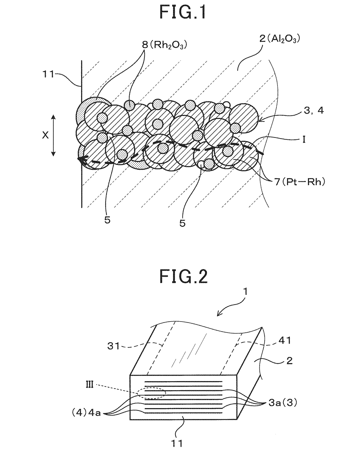
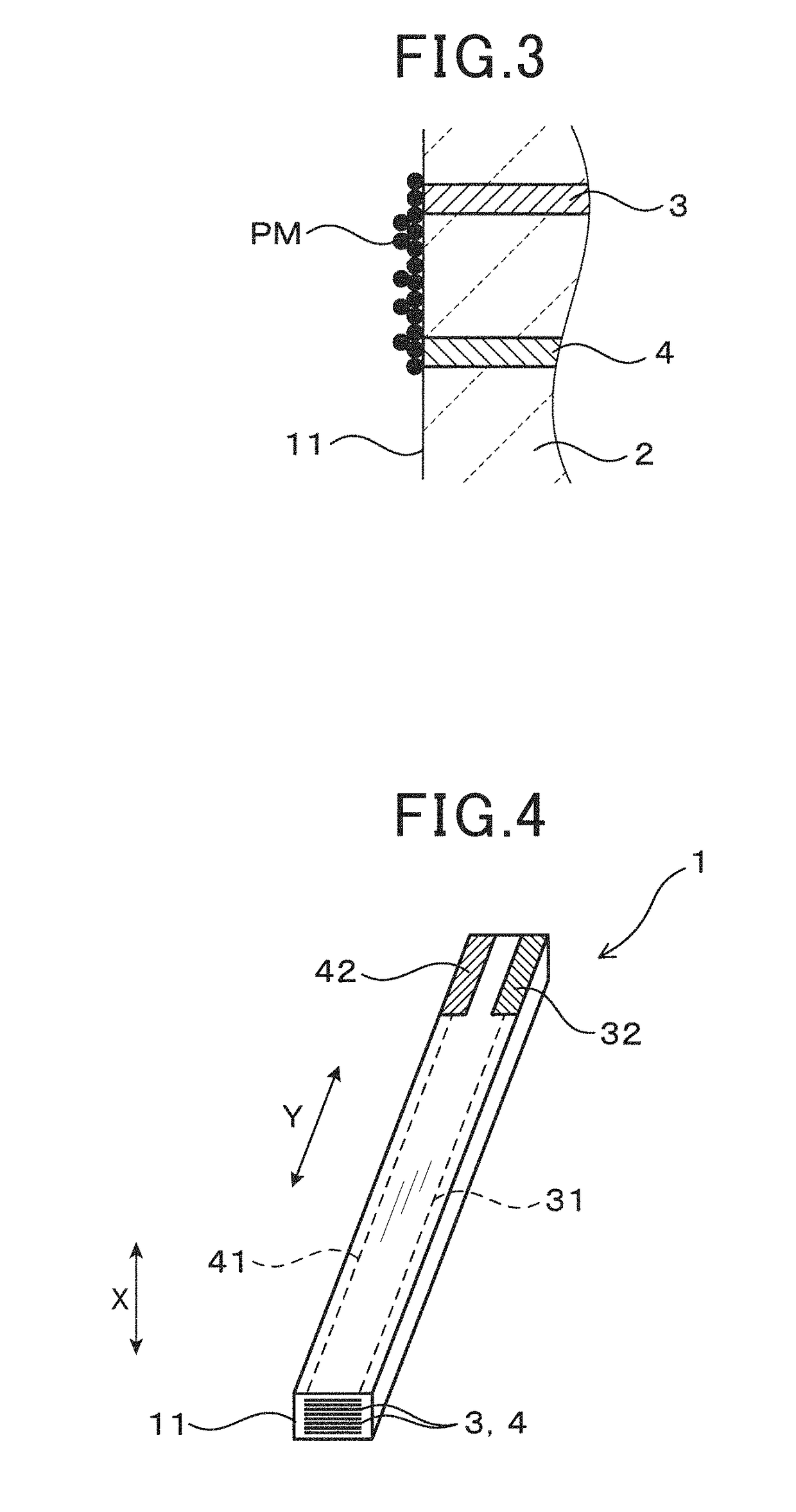
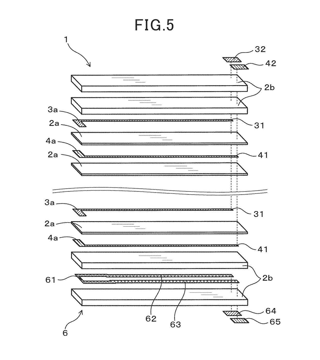
[0040]Next, embodiments of an electrode for a sensor element and a sensor element using the same will be described with reference to the drawings. As shown in FIGS. 1 to 5, this embodiment is an example of application to a particulate matter detection sensor including a laminated type sensor element 1. The particulate matter detection sensor is installed, for example, in the exhaust passage of an internal combustion engine to constitute a part of an exhaust post-treatment device. The sensor element 1 can detect particulate matter (hereinafter referred to as PM) as a specific substance contained in the gas to be measured. The gas to be measured is, for example, a combustion exhaust gas discharged from an internal combustion engine containing micro PM including conductive soot and the like.

[0041]As shown in FIGS. 1 to 3, one end face of an insulating substrate 2 of the sensor element 1 serves as a detection face 11. On the detection surface 11, parts of pairing detection electrodes 3,...

second embodiment

[0063]In the first embodiment, one end face of the laminated type sensor element 1 serves as the detection face 11. In addition, the sensor element 1 has a laminated type electrode structure in which electrode films of the plurality of detection electrodes 3 and 4 are embedded in the insulating substrate 2 like layers. A part of the plurality of pairing detection electrodes 3 and 4 is referred to as a first group and the remaining plurality of pairing detection electrodes 3 and 4 are referred to as a second group. As shown in FIGS. 8 to 10 as the second embodiment, in the sensor element 1, it can also be a printed type electrode structure in which the first group is printed on the surface that is going to be the detection face 11 of the insulating substrate 2, and the second group is embedded. The basic configuration of the sensor element 1 is the same as that of the first embodiment, and mainly the differences from the first embodiment will be described below.

[0064]In this embodime...

experimental example 1

[0070]Next, the sensor element 1 of the first embodiment was fabricated by the method described above, and the variation in the electrode resistance of the detection electrodes 3, 4 was examined by a durability test. For the detection electrodes 3, 4, an electrode material was used. The electrode material was obtained by adding void forming particles made of resin beads to alloy particles 7 of a Pt—Rh alloy, an aggregate of alumina, and an electrode paste. The electrode paste is formed by mixing and kneading an organic solvent with an organic binder. The alloy particles 7 were prepared by mixing an acid solution containing Pt ions and Rh ions, and causing a reduction reaction with a reduction agent. At this time, the amounts of Pt ions and Rh ions were adjusted to vary the percentage by mass of Pt and Rh in the range of Pt: 98 mass % to 69 mass %, Rh: 2 mass % to 31 mass %. This is the ratio on the assumption that the total amount of Pt and Rh is 100 mass %.

[0071]Further, the amount...


PUM

PropertyMeasurementUnit
particle diameteraaaaaaaaaa
softening temperatureaaaaaaaaaa
temperatureaaaaaaaaaa

Abstract

An electrode for a sensor element 1 that detects a specific substance in a gas to be measured, wherein the electrode is embedded in an insulating substrate having a detection face to which the specific substance adheres, the electrode being embedded in such a manner that a part of the electrode is exposed at the detection face, the electrode comprises an alloy of Pt and at least one metal selected from the group consisting of Rh, Ru, Ir, Os, and Pd, and granular voids dispersed among the alloy, and the content of the metal in the alloy is 40 mass % or less, and the number of the granular voids per unit volume of the electrode for a sensor element is 3 / 100 μm3 to 50 / 100 μm3.

Description

TECHNICAL FIELD[0001]The present disclosure relates to an electrode for a sensor element used for a particulate matter detection sensor or the like, and a sensor element using the same.BACKGROUND ART[0002]A particulate matter detection sensor of an electric resistance type is used to detect the amount of particulate matter (PM) in the exhaust gas discharged from an internal combustion engine. The particulate matter detection sensor has an insulating substrate and detection electrodes at least a part of which is embedded in the insulating substrate. The sensor includes a sensor element with a detection face, corresponding to an end face or a side face of the insulating substrate, at which the detection electrodes are exposed.[0003]Over the detection face of such a sensor element, detection electrodes of different polarities are alternately disposed with an insulating layer interposed therebetween. An electrostatic field is formed by applying a voltage between these electrodes. As a r...

Claims


Application Information

Patent Timeline
Patent Type & Authority Applications(United States)
IPC IPC(8): G01N27/12
CPCG01N27/12G01N2015/0046G01N15/0656G01N15/0606G01N15/06G01N27/125F01N11/007G01M15/102G01N27/04
Inventor NOGUCHI, MAKOTOSUZUKI, SATOSHI
Owner DENSO CORP
Learn More