
Secondary cooling method and secondary cooling device for casting product in continuous casting

a cooling device and cooling method technology, applied in the direction of spray-type cooling, can solve the problems of uniform cooling in the width direction of casting products, subjected to overcooling, and overcooling, and achieve the effects of improving cooling efficiency of secondary cooling, high cooling performance, and increasing casting speed

Active Publication Date: 2018-12-13
NIPPON STEEL CORP
View PDF2 Cites 2 Cited by
  • Summary
  • Abstract
  • Description
  • Claims
  • Application Information

AI Technical Summary

Benefits of technology

This patent is about a method and device for cooling a casting product in continuous casting. The method involves using a stable transition boiling region with high cooling performance, which improves the efficiency of the cooling process. This allows the casting speed to increase without increasing the amount of coolant and also reduces the occurrence of surface cracking and temperature unevenness. The device includes a cooling system that ensures the casting product is cooled uniformly in a width direction, which prevents centre segregation.

Problems solved by technology

Spray-type cooling has a problem of overcooling due to so-called dripping water and standing water.
When cooling water jetted from the spray nozzles interferes with dripping water or standing water, the interference portion is subjected to overcooling, which makes cooling ununiform in a width direction of the casting product.
Moreover, in the case of a spray type, water is splattered by jetting water to a hot casting product, and jetted water is not efficiently used, which limits cooling performance.

Method used


Image

  • Secondary cooling method and secondary cooling device for casting product in continuous casting
  • Secondary cooling method and secondary cooling device for casting product in continuous casting
  • Secondary cooling method and secondary cooling device for casting product in continuous casting

Examples


Embodiment Construction

[0069]An embodiment of the present invention is described below.

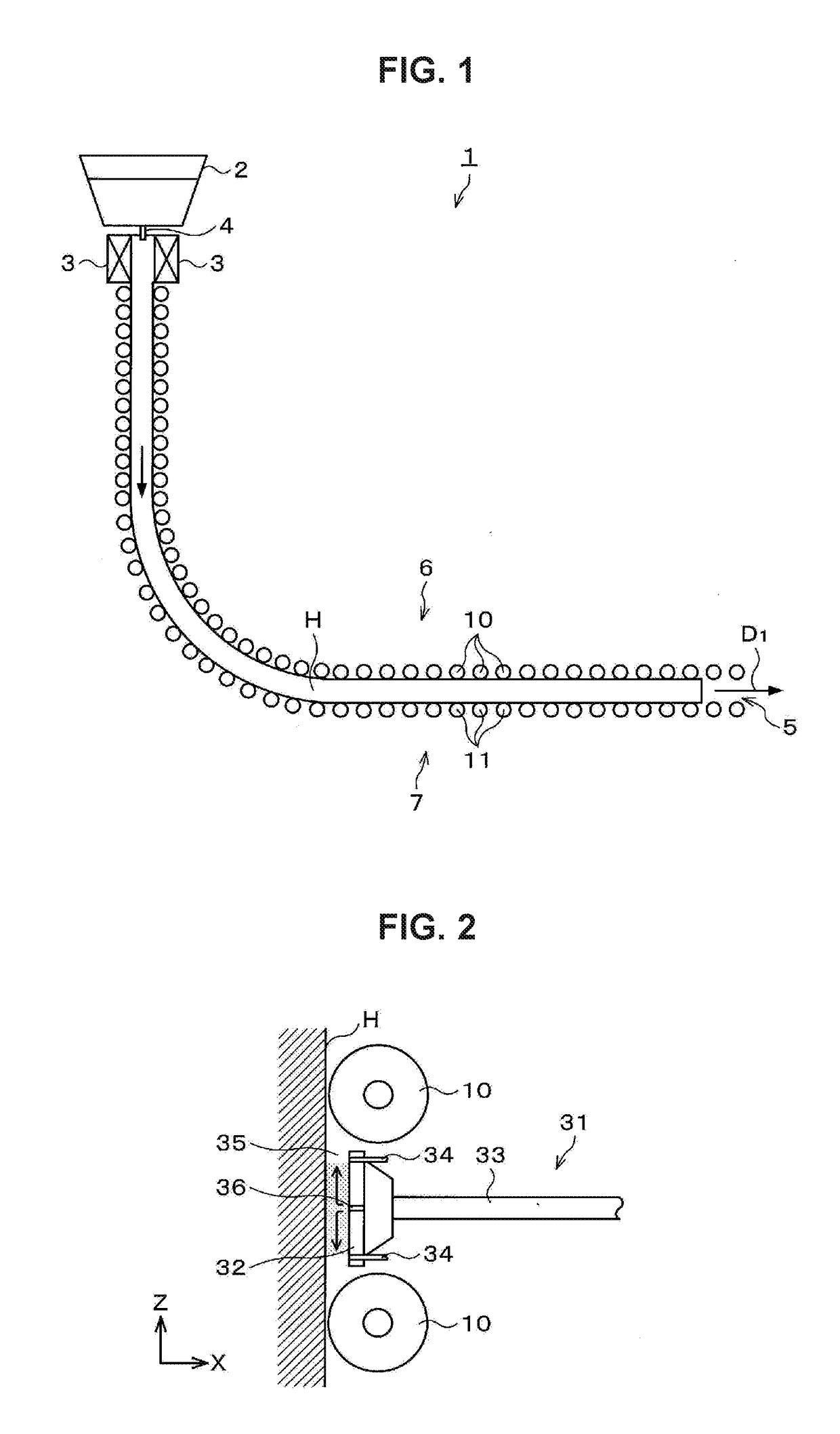
[0070]First, an overall configuration of a continuous casting machine is described with reference to FIG. 1. FIG. 1 is an explanatory diagram schematically illustrating a configuration of a continuous casting machine 1 according to the present embodiment.

[0071]Note that types of continuous casting machines include various types. Examples include (a) a vertical type in which a mold and a support roll are arranged vertically, (b) a vertical bending type in which a casting product solidified while moving vertically is bent horizontally at a solidification completion position, (c) a curved type in which a curved mold and a support roll are arranged on arcs with the same radius and a casting product is bent back horizontally at a solidification end, (d) a vertical gradual bending type in which a mold and an upper support roll group are vertically arranged and then a casting product including unsolidified steel is gradually b...


PUM

PropertyMeasurementUnit
timeaaaaaaaaaa
thicknessaaaaaaaaaa
thicknessaaaaaaaaaa

Abstract

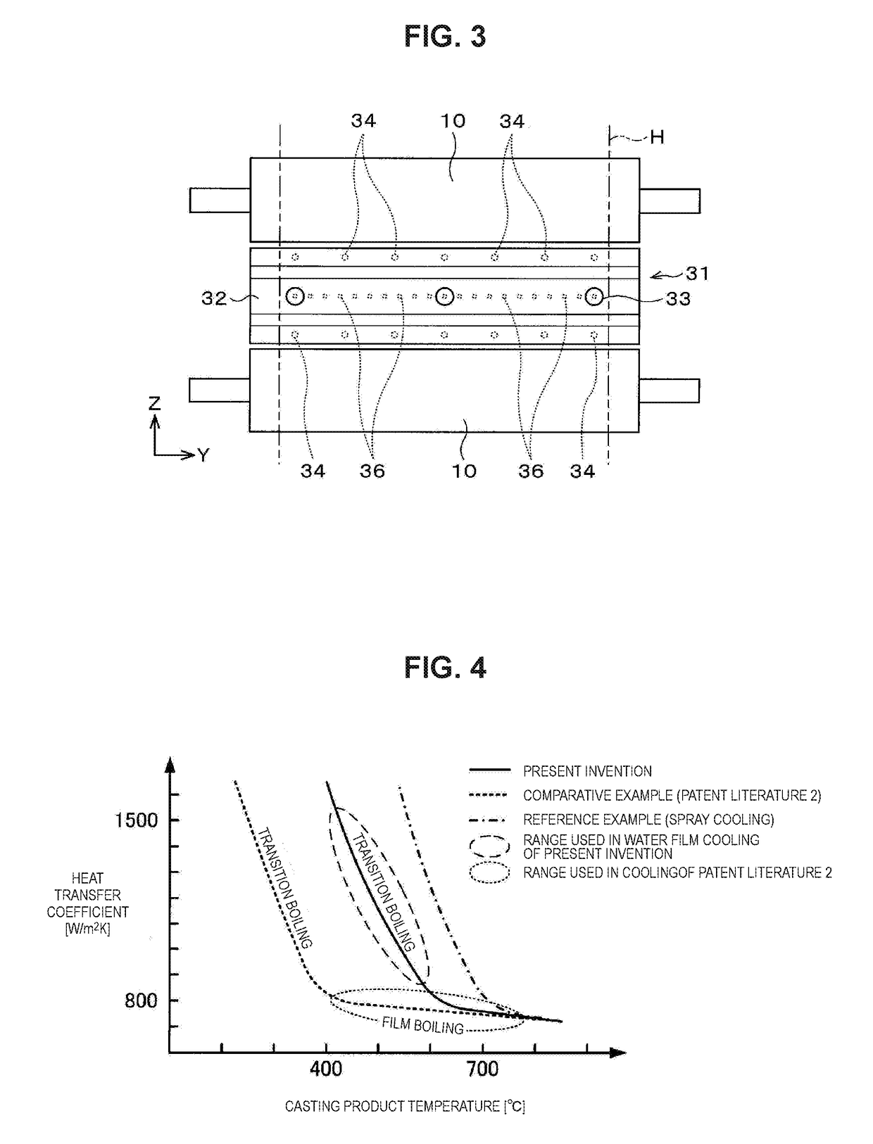
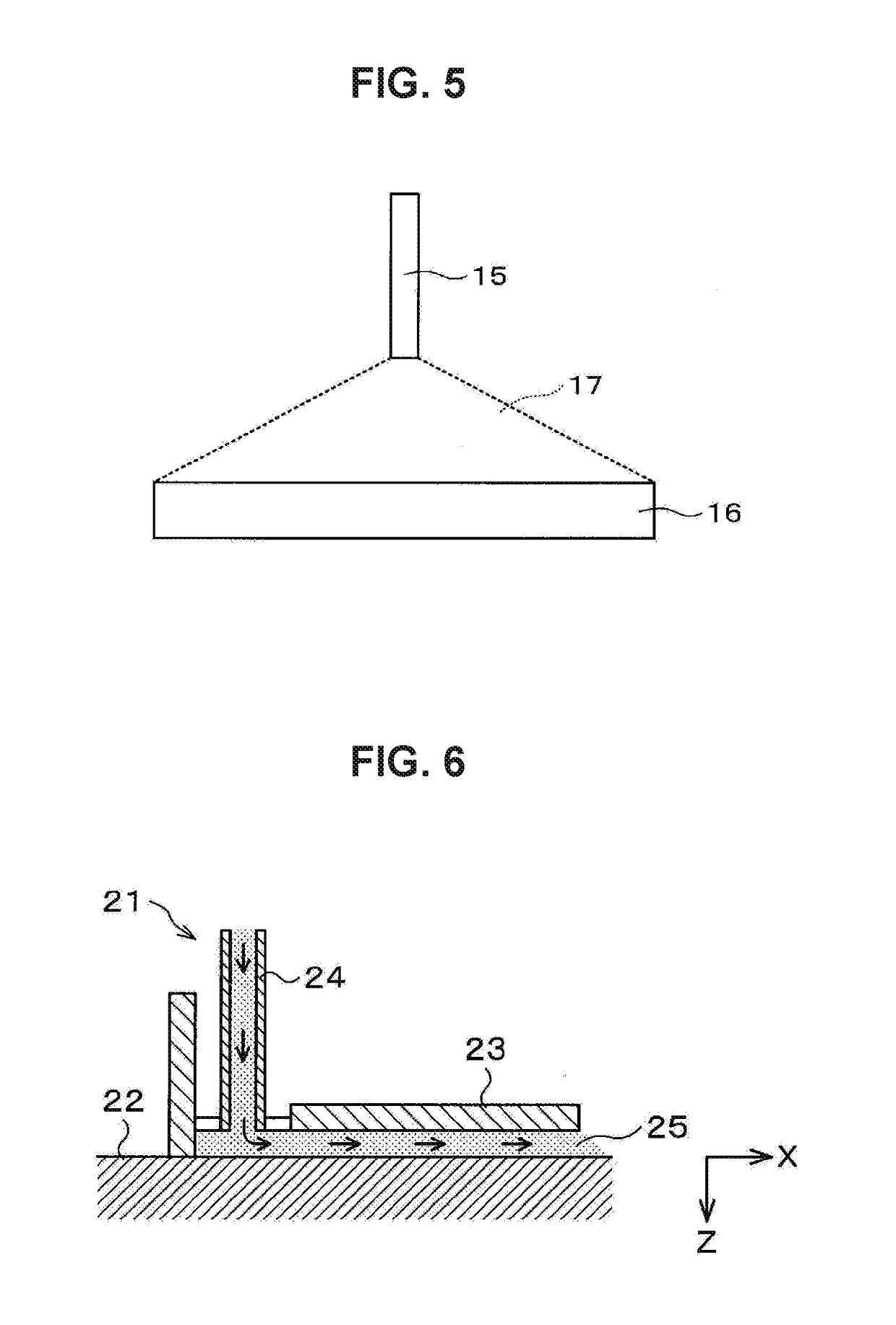
The present invention is a secondary cooling method and a secondary cooling device for a casting product casted in a continuous casting machine, the continuous casting machine including, in a secondary cooling zone below a mold, a plurality of pairs of support rolls that support the casting product from both sides of the casting product in a thickness direction, a cooling device being disposed between support rolls adjacent to each other along a casting direction of the continuous casting machine, the cooling device including a coolant pipe that supplies a coolant, and a coolant guide plate with a flat plate shape for spreading the coolant on the casting product, the coolant guide plate being disposed parallel to and spaced in a perpendicular direction from a surface of the casting product. The coolant is supplied from a coolant supply port provided in the coolant guide plate to a gap between the casting product surface and the coolant guide plate, and the casting product is cooled using the coolant mainly in a transition boiling region.

Description

TECHNICAL FIELD[0001]The present invention relates to a secondary cooling method and a secondary cooling device in performing continuous casting of a casting product in a continuous casting machine.BACKGROUND ART[0002]In continuous casting in the iron and steel industry, conventionally, spray-type cooling has been widely performed as a method for secondary cooling of a casting product. In this secondary cooling method, spray nozzles are arranged between support rolls that convey a casting product, and cooling water is put into a spray form and sprayed on the surface of the casting product for cooling.[0003]Spray-type cooling has a problem of overcooling due to so-called dripping water and standing water. Dripping water is, in a sectional roll serving as a support roll for a casting product, cooling water that falls to the downstream side from a bearing, which does not come into contact with the casting product. Standing water is cooling water that stays in a space surrounded by a ro...

Claims


Application Information

Patent Timeline
Patent Type & Authority Applications(United States)
IPC IPC(8): B22D11/124B22D11/22
CPCB22D11/1246B22D11/225B22D11/124B22D11/1245B22D11/1243
Inventor KUWAUCHI, YUKIFUNAGANE, HITOSHIHAYASHI, SATORU
Owner NIPPON STEEL CORP
Learn More