Method for fabricating polymeric wavelength filter

a wavelength filter and polymer technology, applied in the direction of instruments, optical elements, vacuum evaporation coating, etc., can solve the problems of unfeasible narrow transmission bandwidth, long coupling length, and significant grating depth affecting the performance of optical devices, and achieve good aspect ratio of grating pattern

Inactive Publication Date: 2010-04-08
CHINA UNIV SCI & TECH
View PDF3 Cites 16 Cited by
  • Summary
  • Abstract
  • Description
  • Claims
  • Application Information

AI Technical Summary

Benefits of technology

[0006]The technique of forming gratings patterns on the UV polymer simply involves three processing steps. First, a gratings pattern is holographically exposed using a two-beam interference pattern on a positive photo-resister film. A 20-nm-thick nickel thin film is then sputtere

Problems solved by technology

In surface grating applications, the grating depths significantly affect the performance of optical devices.
If grating-assisted waveguides are used in optical filter applications, shallow grating, which will result in small coupling coefficients, will lead to an unfeasibly narrow transmission bandwidth and will therefore require a long coupling length to attain a specific transmission.
Furthermore, when optical light sources with a short wavelength are used in optical components, the higher-order peaks of propagation modes cannot be eliminated from the filter; this will result in low efficiency of the first-order peak of propagation modes if the aspect ratio between the depth and the period of gratings is low.
However, it has certain drawbacks, as explicitly mentioned in Ref. 15. These drawbacks may restrict the use of this method in fabricating a Bragg grating filter.
In these techniques, the RIE process transfers a gratings pattern from the top polymer layer to the core underneath and it increases the difficulty of obtaining accurate and smooth waveguide gratings.
88]. However, the main drawbacks of h-PDMS are the brittle nature of h-PDMS and the thermal curing requirements of such mate
rial. Because the relatively low toughness of the h-PDMS made relief features with these geometries susceptible to fracture, elements of h-PDMS tended to fail due to fracture of the relief features during fabrication of the elements or during their use, particularly in molding applica
er ease. In addition, the theoretical limit of the frequency of the interference pattern produced by two intersecting beams is half the wavelength of the incid
Sol-gel hybrid (SGH) materials can be easily used for the fabrication of grating diffraction by the holographic interferometric technique; however such material cannot be used for the fabrication of gratings pattern with high aspect ratios, and since they are brittle material, they find applications.

Method used


Image

  • Method for fabricating polymeric wavelength filter
  • Method for fabricating polymeric wavelength filter
  • Method for fabricating polymeric wavelength filter

Examples


Embodiment Construction

I. The Concept of the Present Invention

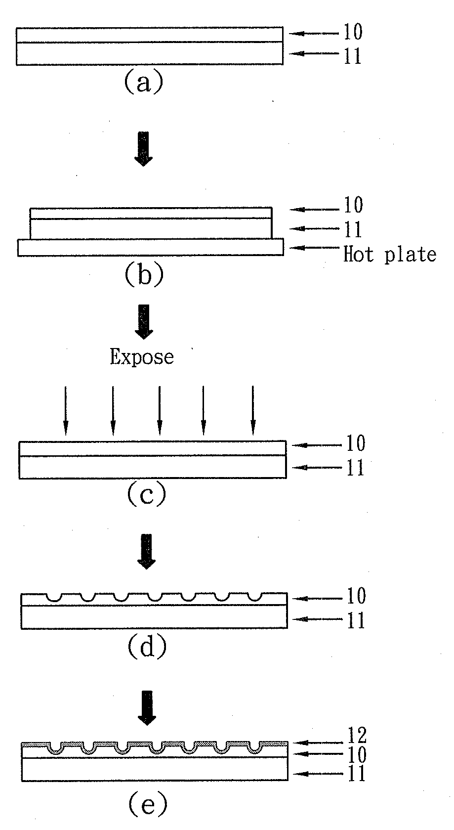
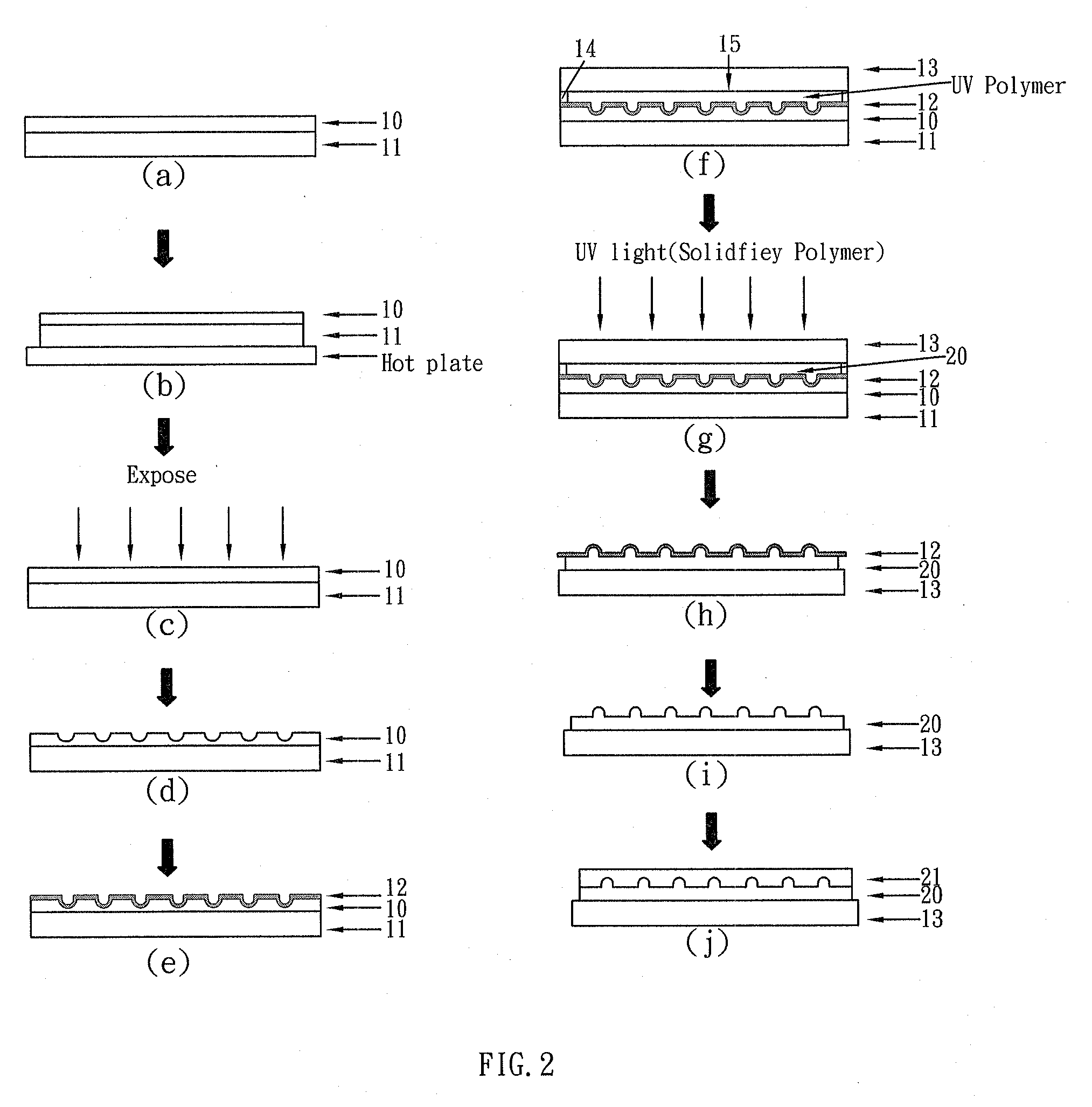
[0017]The present invention of forming gratings patterns on the UV polymer involves three processing steps. First, a gratings pattern is holographically exposed using a two-beam interference pattern on a positive photo-resister film. A 20-nm-thick nickel thin film is then sputtered onto the positive photo-resister film to obtain a nickel mold having grating pattern. This nickel mold on the photo-resister film then can be subsequently used to transfer the final gratings pattern onto a UV polymer (UV cure epoxy polymer). The following sections describe the process involved in grating fabrication.

II. The Basic Fabrication Process of the Present Invention

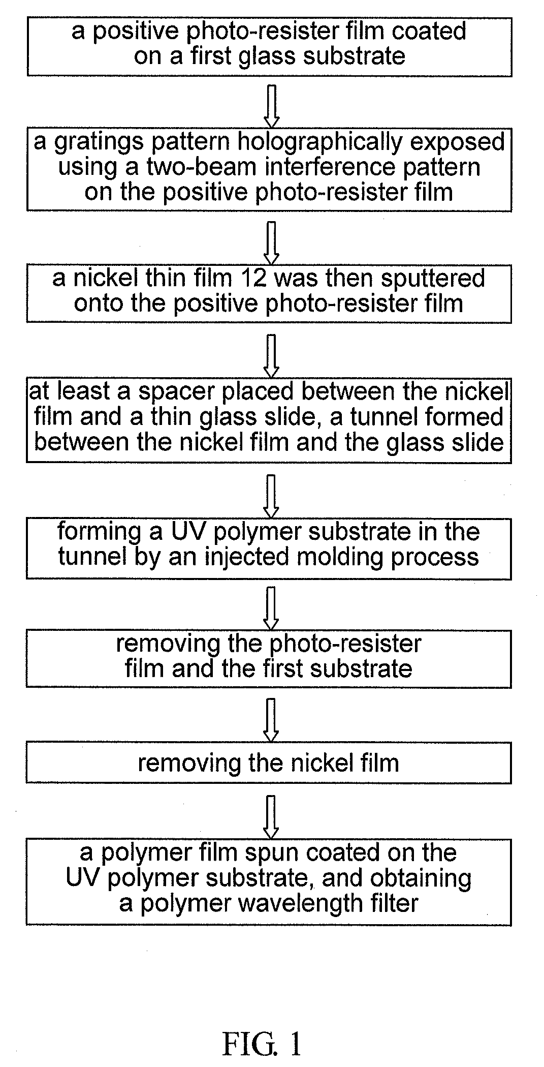
[0018]Referring to FIGS. 1 and 2, the basic method for fabricating the polymer wavelength filter comprises following steps:

[0019](A) a positive photo-resister film 10 coated on a first glass substrate 11;

[0020](B) a gratings pattern holographically exposed using a two-beam interference pattern on t...


PUM

PropertyMeasurementUnit
Temperatureaaaaaaaaaa
Lengthaaaaaaaaaa
Lengthaaaaaaaaaa

Abstract

The present invention discloses a method for fabricating polymeric wavelength filter, which method for forming gratings patterns on the UV polymer involves three processing steps. First, a gratings pattern is holographically exposed using a two-beam interference pattern on a positive photo-resister film. A 20-nm-thick nickel thin film is then sputtered onto the positive photo-resister film to form a nickel mold. This nickel mold on the photo-resister film then can be subsequently used to transfer the final gratings pattern onto a UV cure epoxy polymer. Whereby, a polymer film can be spun coated on the cure epoxy substrate so as to simplify the fabrication process for obtaining a polymer wavelength filter with good aspect ratio of gratings pattern.

Description

FIELD OF THE INVENTION[0001]The present invention relates to a method for fabricating polymeric wavelength filter, especially to a technique that uses the micro-molding process to simplify the fabrication process for obtaining a polymer wavelength filter with good aspect ratio of gratings pattern.BACKGROUND OF THE INVENTION[0002]Gratings are used in integrated optics for several purpose, including wavelength filtering, sensing, optical measuring technique, spectral narrowing of laser output, optical power coupling in waveguide systems, etc. In particular, surface grating with high diffraction efficient can be utilized in many applications, such as holographic image storage, liquid crystal anchoring, optical filters, or resonant couplers. In surface grating applications, the grating depths significantly affect the performance of optical devices. If grating-assisted waveguides are used in optical filter applications, shallow grating, which will result in small coupling coefficients, w...

Claims


Application Information

Patent Timeline
IPC IPC(8): C23C14/00
CPCG02B6/138G02B6/124
Inventor LEE, KUN-YICHUANG, WEI-CHINGLIN, YEN-JUEILEE, CHENG-CHELEE, WEI-YU
Owner CHINA UNIV SCI & TECH
Why Eureka
Try Eureka