
Transmission apparatus and transmission method

a transmission apparatus and transmission method technology, applied in the field of transmission apparatus and transmission method, can solve the problems of inability to specifically disclose the control method using the frame display interval, processing cannot keep up with tasks for stream transmission at high-bit rate, and too late real-time processing

Inactive Publication Date: 2010-04-01
PANASONIC CORP
View PDF22 Cites 28 Cited by
  • Summary
  • Abstract
  • Description
  • Claims
  • Application Information

AI Technical Summary

Benefits of technology

This approach ensures real-time communication, high-quality transmission of both priority and non-priority data, reduces CPU load, and prevents system failures by prioritizing high-priority data effectively and managing data packets efficiently, thereby maintaining stable system operation and accurate shaping.

Problems solved by technology

However, the conventional example fails to specifically disclose how to perform control by utilizing the frame display interval.
However, the above-mentioned conventional configuration has the following problems.
For that reason, there is a problem that processing cannot keep up with tasks for stream transmission at high-bit rate.
Moreover, as the PCI bus is used as a common bus, real-time data with higher priority to be transmitted or received and data with lower priority exist together, thereby causing a problem that real-time processing is too late.
Firstly, as data rate for stream transmission of video data is essentially very high, the CPU can exceed its performance limit.
Secondly, due to overhead at the switching of thread (or referred to as task or process), CPU performance is lowered substantially, and due to memory copy repeated many times at processing, CPU throughput allocated to video transmission is limited.
Specifically, in the first conventional example, there causes a problem that the speed at which the CPU generates the ethernet frame cannot keep up with the data rate of the data to be transmitted (video data in this example) at transmission of the NIC and therefore the untransmitted video packet occurs, resulting in broken video image.
Further, there is another problem that even when the ethernet frame can be generated at required data rate, transfer of the ethernet frame from the memory to the NIC cannot be completed in time.
Further, there is another problem that so-called shaping processing in which the video packet need to be transmitted at regular timings depends on the CPU (depends on software with variation in processing timing), so that accurate shaping cannot be achieved.
Moreover, at the time of receipt of the NIC, there is a possibility that the CPU cannot carry out switching to the thread for processing the receive frame and capture the incoming ethernet frame into the memory in time, thereby missing data in the NIC (abandonment of ethernet frame).
Althernatively, even when the ethernet frame can be taken into the memory, the CPU can take too long for protocol processing, thereby failing to transmit data in real time.
Moreover, as another problem, since task management depends on the OS, a high priority is not necessarily given to processing of the high-priority data such as video signal over the low-priority data such as management information.
Use of high-performance CPU can increase its throughput, but it is not a fundamental solution to these problems.
In addition, the high-performance CPU consumes a large volume of electric power.
In the case of insufficient heat radiation especially in equipment with built-in CPU, the equipment can proper improper operations.
The high-performance CPU also has a problem of being expensive.
These problems are aggravated in the case where the CPU performs processing of additional information such as management information in addition to transmission of video data.
The problems on network processing of the above-mentioned problems relating to the CPU essentially arise from the fact that network processing in the general operating systems is performed in sub-layers of the OSI architecture model in a sequential order.
Such processing in the order of layers causes processing overhead, imposing a burden on the CPU (software processing).
The above-mentioned problems occur at the transmission side of ethernet.
However, it discloses no method of controlling the generated real-time data packet and other packet generated in the processor.
In the case of controlling these packets in the conventional method, the following problems arise.
The first problem is that the real-time data packet is not necessarily transmitted by priority.
Specifically, in the case where a large number of non-real time data packets are generated in the second conventional example, transmission of the real-time data packets is limited, resulting in that real-time characteristic cannot be ensured.
As the second problem, it cannot be ensured that non-real time data is transmitted without system failure while giving a priority to transmission of real-time data.
In the second conventional example, however, no method of controlling transmission of real-time data and other data is disclosed.
In other words, the second conventional example has a problem that quality of real-time data must be lowered to ensure transmission of the other data.
Therefore, the second conventional example has a problem that real-time data can be transmitted only to the fixed address hold by the parameter setting means 29 in advance.
For that reason, there also causes another problem that port number cannot be set flexibly, for example, in the case of negotiating the port number of upper UDP protocol, not limited to ARP processing.
Therefore, in the case where the amount of real-time data to be transmitted in the isochronous zone is smaller and the amount of ordinary data to be transmitted is larger than the respective allocated transfer capability, the transmission zone is wasted.
Similar problem also arises in the case where the amount of ordinary data to be transmitted in the non-isochronous zone is smaller and the amount of real-time data to be transmitted in the isochronous zone is larger than the respective allocated transfer capability.
That is, the third conventional example has a problem that the proportion between real-time data and ordinary data cannot be changed flexibly.
The third conventional example has another problem that when real-time data to be transmitted generates during the time allocated to the non-isochronous zone, data transmission has to be postponed until the next isochronous zone, causing delay in transmission.
Many applications are affected seriously by the delay of real-time data.
As these applications require transmission of real-time data with short delay, it is a major problem.
This delay problem occurs in transmission of ordinary data in the same way.
When ordinary data to be transferred generates in the isochronous zone, data transmission has to be postponed until the next non-isochronous zone, causing a similar delay problem.
In this case, however, when the time necessary for processing of the video data exceeds the time interval of the video frame even if only slightly, the problem such as loss of real-time characteristic occurs, thereby causing break in image.
Therefore, using the video frame as reference means control based on the extreme broad reference, causing the following problem.
However, if the delay has already become unrecoverable at the point when burst transfer is started, transmission of one frame cannot be terminated within its video frame time (the time period during which processing must be finished to maintain real-time characteristic), causing a break in image.
This problem is apt to occur especially when video data and non-video data are transmitted together.
In this case, even if a short UDP / IP packet becomes prepared for transmission before transmission of the TCP / IP packet is completed, transmission of the UDP / IP packet cannot be started until termination of transmission of the TCP / IP packet.
As a result, transmission of the UDP / IP packet is delayed, thereby to cause a problem of damaging real-time characteristic of the video data.
Essentially, this problem results from the fact that transmission priority of video data is not enough higher than that of non-video data in the fourth conventional example.
For that reason, the application that has tried to transmit the TCP / IP packet times out, thereby causing failures in stable system operation.
Essentially, the above-mentioned problem arises from the simple algorithm of transmitting non-video data (TCP / IP packet) only when the UDP / IP packet is not transmitted.

Method used


Image

  • Transmission apparatus and transmission method
  • Transmission apparatus and transmission method
  • Transmission apparatus and transmission method

Examples


first embodiment

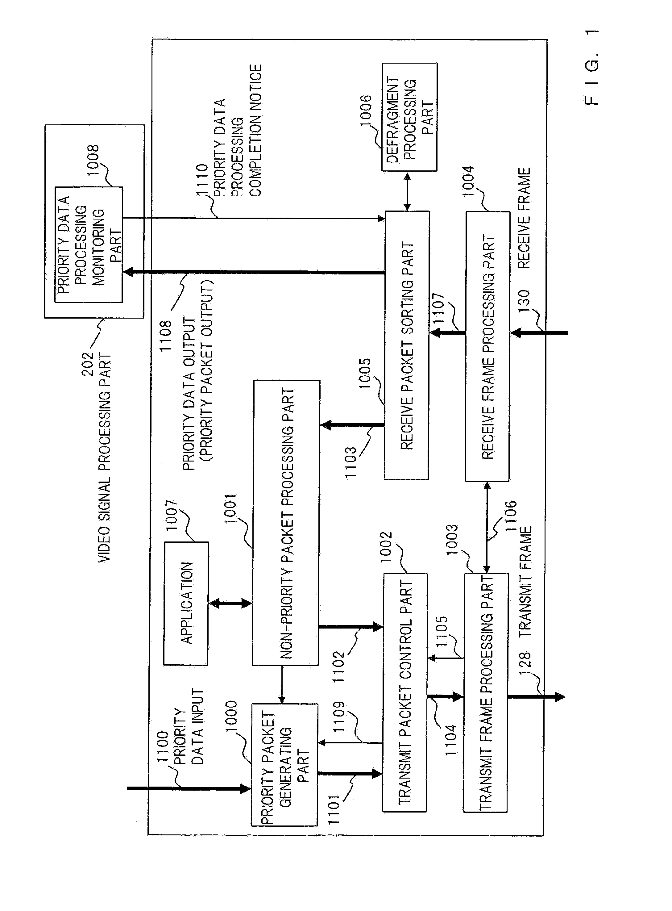
[0130]A transmission apparatus and a transmission method in accordance with the first embodiment will be described. The transmission apparatus of the first embodiment shown in FIG. 1 has the priority packet generating part 1000, the non-priority packet generating part 1001, the transmit packet control part 1002 and the transmit frame processing part 1003. In the first embodiment, a transmission system is described.

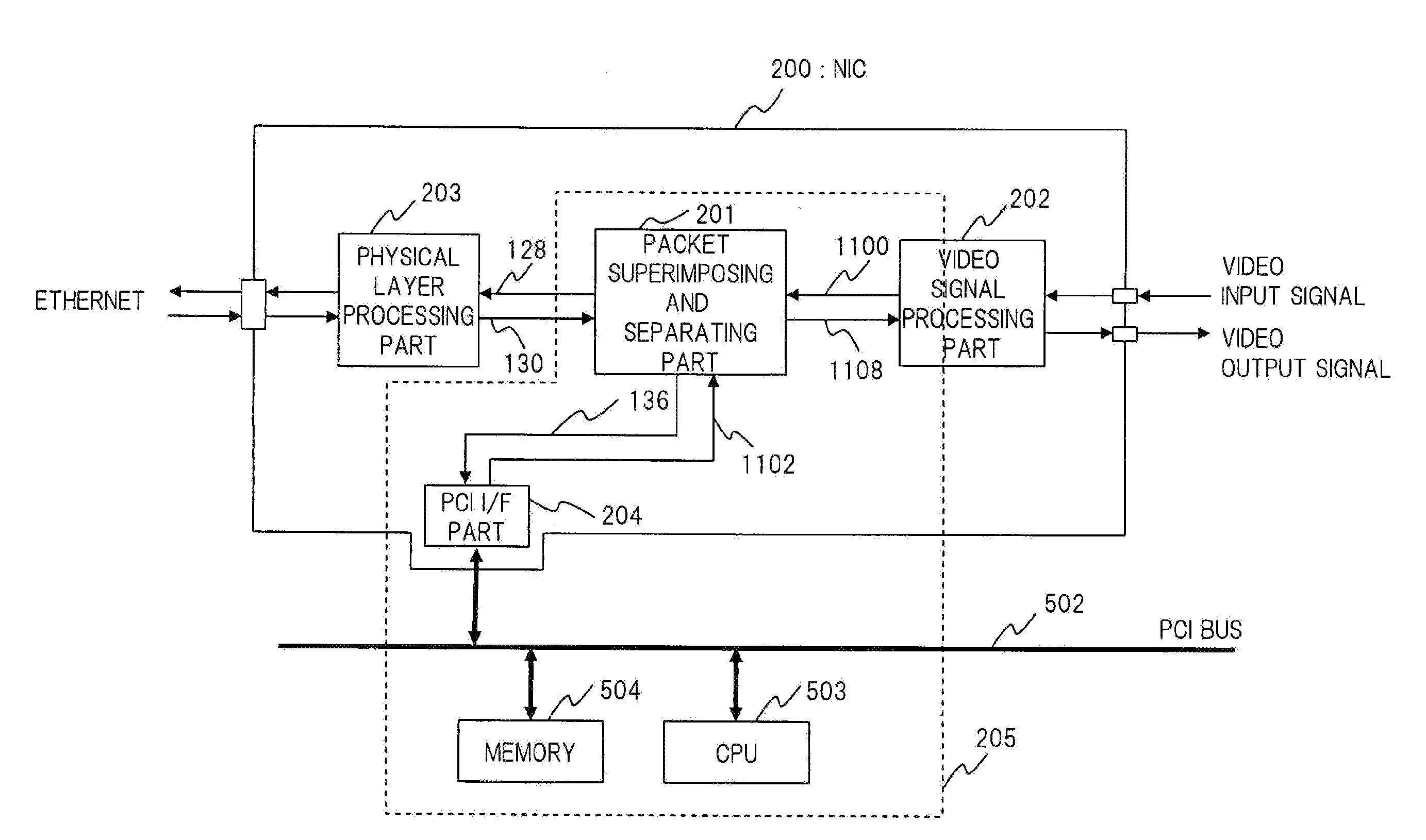
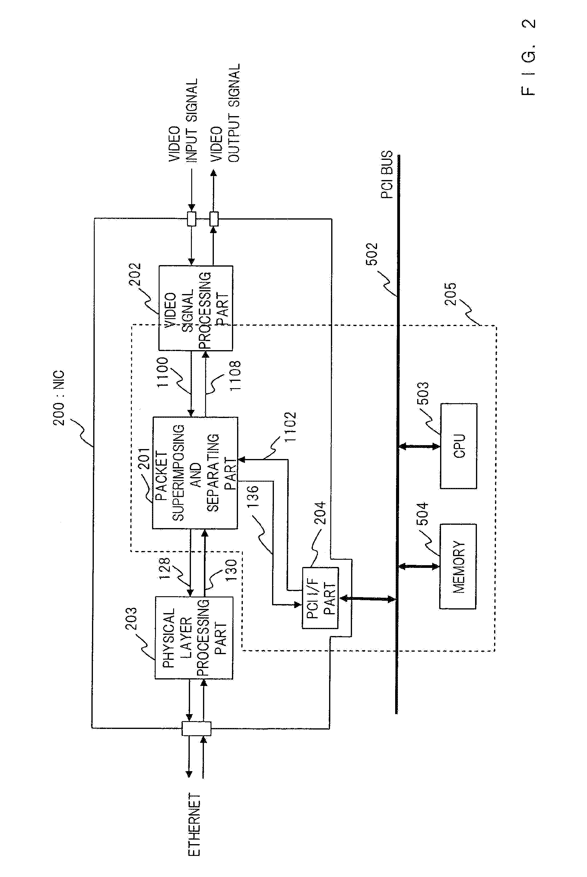
[0131]In this embodiment, the video data shown in FIG. 3 is input as an input priority data 1100 (shown in also FIG. 2). For stream transmission of video data in real time, the video data need to be processed in preference to data requiring no real-time characteristic.

[0132]In the first embodiment, a transmit margin time is generated by controlling transmission of the priority packet. The “transmit margin time” means the period during which real-time characteristic of priority data stored in the priority packet cannot be impaired even if the non-priority packet is transmit...

second embodiment

[0179]A transmission apparatus and a transmission method in accordance with a second embodiment will be described. In the second embodiment, the transmit system and the receive system is described.

[0180]In carrying out IP transmission, ARP as a protocol for obtaining a physical address (MAC address) of ethernet from a destination IP address is used.

[0181]FIG. 8 is a diagram for showing details of UDP, IP and ethernet protocol headers in accordance with the embodiment of the present invention. In carrying out IP transmission, the transmission apparatus of the embodiment resolves a destination MAC address 8100 from a destination IP address 8011 in FIG. 8 and stores it in the ethernet header 3004 in FIG. 3 to constitute a packet.

[0182]This ARP is performed through two-way communication. Typically, address is resolved by using a processor and a correspondence table of the destination IP address and the destination MAC address is held in the memory. As ARP is not a processing requiring r...

third embodiment

[0190]A transmission apparatus and a transmission method in accordance with the third embodiment will be described. A receive system is described in the third embodiment.

[0191]In FIG. 1, the transmission apparatus of the third embodiment has the receive frame processing part 1004, the receive packet sorting part 1005 and the non-priority packet processing part 1001.

[0192]The receive frame processing part 1004 receives the receive frame 130 in which the priority packet and the non-priority packet exist together from the physical layer processing part 203 in FIG. 2, processes only valid ethernet frame to be received therein and outputs a receive frame 1107.

[0193]The receive packet sorting part 1005 receives input of the receive frame 1107 and sorts it into a priority packet 1108 and a non-priority packet 1103. The method of sorting packets in the receive packet sorting part 1005 will be described below.

[0194]In this embodiment, UDP / IP is used in transmission of the priority packet. Lo...


PUM


Abstract

A transmission apparatus for stably transmitting or receiving data of high priority is provided. In the transmission apparatus of the present invention, processing of the priority packet to be transmitted and processed by priority and processing of the non-priority packet are conducted separately. At transmission side, the above-mentioned priority packet is transmitted by priority by making its average transmission interval shorter than its average generation interval, and said non-priority packet is transmitted during the transmit margin period caused by the above-mentioned processing. At receive side, in the layer of processing the receive frame as a layer lower than the layer of processing the priority packet and non-priority packet, the priority packet and the non-priority packet is sorted based on the communication protocol header of the receive packet stored in the receive frame, and processing of the priority packet and that of the non-priority packet are conducted separately.

Description

TECHNICAL FIELD[0001]The present invention relates to a transmission apparatus and a transmission method that handle priority packets to be transmitted or received by priority (priority packets) and other non-priority packets (non-priority packets).BACKGROUND ART[0002]For transmission of data having real-time characteristic such as video signal through a communication network including ethernet, it is generally performed to install a board for video signal processing (video card) and a network interface card into a PCI (Peripheral Components Interconnect) bus of personal computer and to transmit packets according to the network protocol such as Internet Protocol (hereinafter referred to as “IP”), User Datagram Protocol (hereinafter referred to as “UDP”) or Transmission Control Protocol (hereinafter referred to as “TCP”).[0003]FIG. 11 is a block diagram of a prior art transmission system in which video signals are transmitted through ethernet. FIG. 11 shows an ethernet network interf...

Claims


Application Information

Patent Timeline
Patent Type & Authority Applications(United States)
IPC IPC(8): H04L12/24H04L12/28H04L29/06
CPCH04L12/5693H04L47/10H04L69/16H04L47/2433H04L47/6215H04L47/22H04L47/50
Inventor HIGASHIDA, MASAAKI
Owner PANASONIC CORP
Learn More