
Apparatus for imaging single molecules

an apparatus and single-molecule technology, applied in the field of apparatus for single-molecule imaging, can solve the problems of limiting the maximum speed possible, limiting the application of microarray analysis techniques, and few approaches that apply these techniques to microarray analysis, so as to reduce the possibility of unnecessary scan area, reduce the effect of background rejection and finding an area of interest quickly

Inactive Publication Date: 2010-02-04
OXFORD GENE TECH IP
View PDF3 Cites 20 Cited by
  • Summary
  • Abstract
  • Description
  • Claims
  • Application Information

AI Technical Summary

Benefits of technology

[0035]The use of a dry microscope objective, corrected for a cover slip thickness of zero, means that neither the use of immersion liquid nor the use of cover slips is required, and the sample is less likely to be damaged.
[0045]Furthermore, the translation stage may be movable in a direction substantially parallel to the optical axis. Alternatively, or additionally, the objective lens may be movable in a direction substantially parallel to the optical axis. In the case of infinity-corrected optics, it is preferable to move the objective lens rather than the translation stage along the optical axis because the movable mass is typically smaller, making the translation step easier and faster.
[0050]When the sample exhibits a flat surface, for example, a microarray with a microscope slide as its solid support, the speed of the focusing may further be improved by use of a predictive focusing method. With such a method, the distance correction between the microscope objective and the test surface that is necessary due to re-positioning of the sample may be derived from previous corrective requirements. When this focusing correction is applied while the sample is moving, the subsequent autofocus operation may need to apply a smaller correction, thus making it faster and more precise.
[0067]The scanner is preferably implemented for single-colour use such that there is a single excitation wavelength band and the detector is configured to detect the wavelength band associated with the emission of a single fluorescent species. Radiation in a single excitation wavelength band could be provided by a light source in combination with a wavelength selector. The wavelength selector could be, for example, a filter, a filter set, an acousto-optical modulator, a combination of prisms, a combination of diffractive optical elements, a combination of gratings, etc. However, the scanner could be implemented with a multi-colour, for example dual-colour, 4-colour or 6-colour, setup for imaging two-colour samples, for example microarrays, where a comparison of two different samples is multiplexed into the optical colour space, or multi-colour enhanced sample, for example microarrays, where the target molecules or alternatively the probe-target complexes have been co-labelled with more than one colour fluorescent dye molecule (possibly through the use of intercalating dyes). The latter configuration could be used for more efficient background rejection, such as non-specific binding events of probe molecules to the surface, or contaminating fluorescence, or non-specific binding of free fluorescent tags, labels, dust or other particulate contamination.
[0068]The scanner may be configured to function at two or more different spatial resolutions: a first, lower resolution useful for finding an area of interest quickly, and a second, higher resolution useful for performing an optimum resolution scan that takes longer. This configuration allows more meaningful data to be captured, cutting down on possibly unnecessary scan area. Such a configuration also helps to reduce disk space, time spent on analysis, and time spent on the scan.

Problems solved by technology

However, there are few approaches that apply these techniques to microarray analysis.
A number of documents identify that this process, often called image tiling has severe drawbacks, in particular in limiting the maximum speed possible.
As an example, a depth of field of 800 nm cannot be maintained over the entire microscope slide without focus adjustments for each image since the microscope slide is not flat enough over its entire area; small tilt angles can cause a sample movement parallel to the optical axis which results in an out-of-focus image.
This, as discussed below, is not desirable for the use in a microarray scanner.
However, the CytoScout™ has a number of weaknesses, technical and otherwise, when it is used as a microarray scanner.
This has serious consequences.
Firstly, the instrument requires a skilled operator for the application of the immersion oil.
Secondly, in order to use oil-immersion optics it is necessary to cover a conventional microarray with a cover slip or to use a special type of microarray support that requires a coverslip instead of the conventionally used microscope slide.
However, covering a microarray with a coverslip potentially damages the array.
This means that standard microarray platforms cannot be used with this instrument.
Their thickness of ˜1 mm requires the implementation of imaging optics with a long working distance, at the expense of detection efficiency.
2005).” It is evident from these statements that researchers have identified a problem with the CytoScout™ (namely that standard microarray slides cannot be scanned with high detection efficiency).
However, the provided solution introduces new practical problems for users for example, inter alia, the use of fragile chips, and the need to change the manufacturing process.
In addition, dye molecules start to bleach when they are struck by free radicals such as oxygen in air.
Consequently, if the dye molecules are exposed to air, they are unstable and the number of photons emitted is reduced.

Method used


Image

  • Apparatus for imaging single molecules
  • Apparatus for imaging single molecules
  • Apparatus for imaging single molecules

Examples


Embodiment Construction

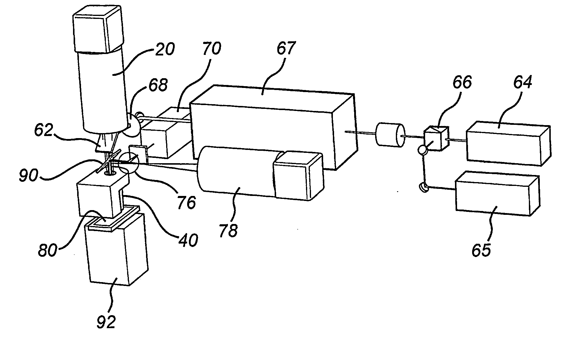
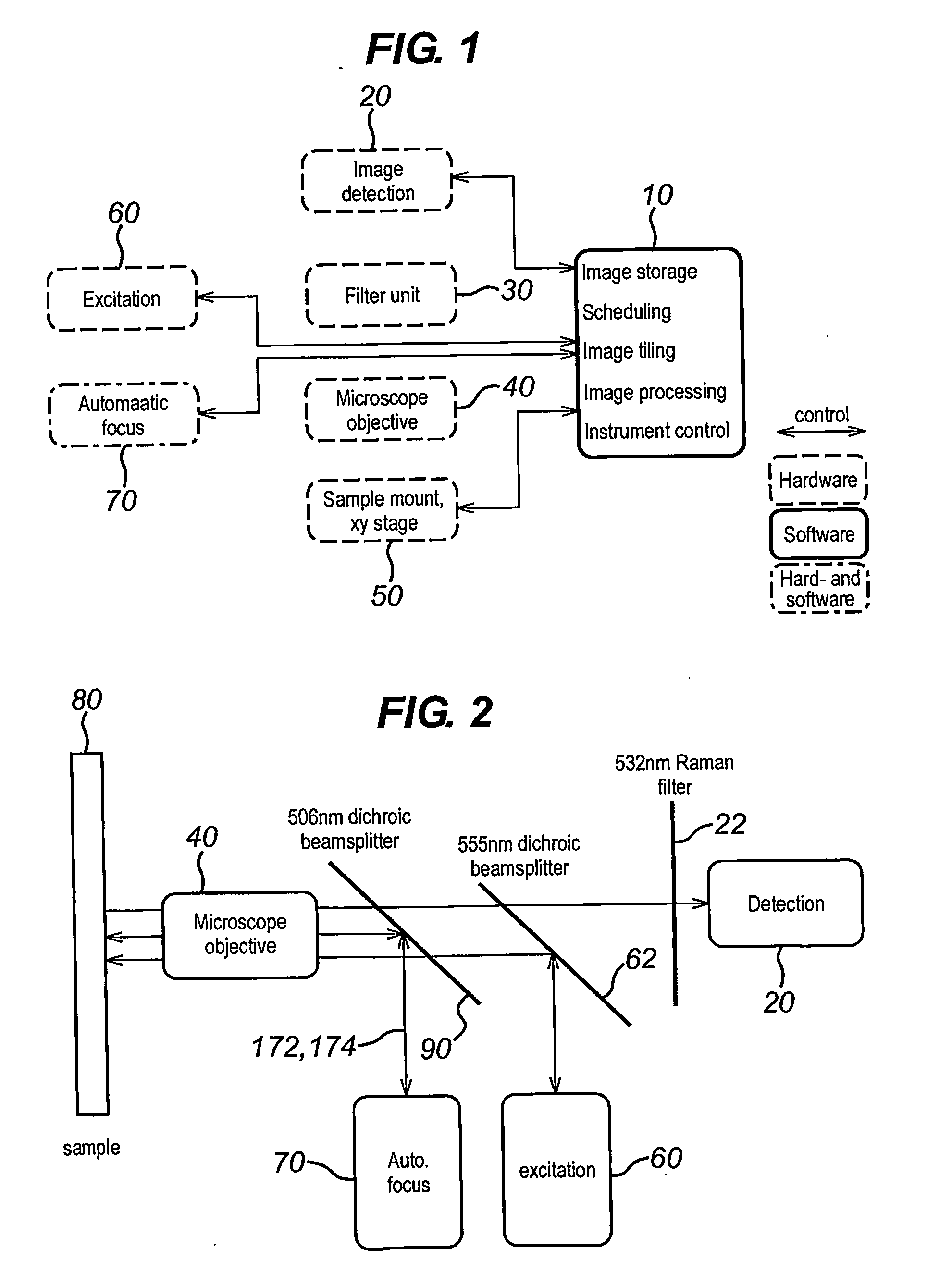
[0094]FIG. 1 shows the components of a single molecule scanner according to an embodiment of the present invention. In particular, the single molecule scanner of FIG. 1 includes software 10 for image storage, scheduling, image tiling, image processing, and instrument control, an image detection unit 20, a filter unit 30, a dry microscope objective 40, a sample positioning unit 50, excitation components 60, and an auto-focus mechanism 70. The image detection unit 20, the sample positioning unit 50, the excitation components 60 and the auto-focus mechanism 70 are controlled by software 10. Operation of the software 10 for image scheduling is described in co-pending United Kingdom patent application no. GB-0618133.3 which is hereby incorporated by reference. The scanner further comprises a storage unit configured to store the data obtained by the control unit in a non-volatile memory such as a magnetic disk drive.

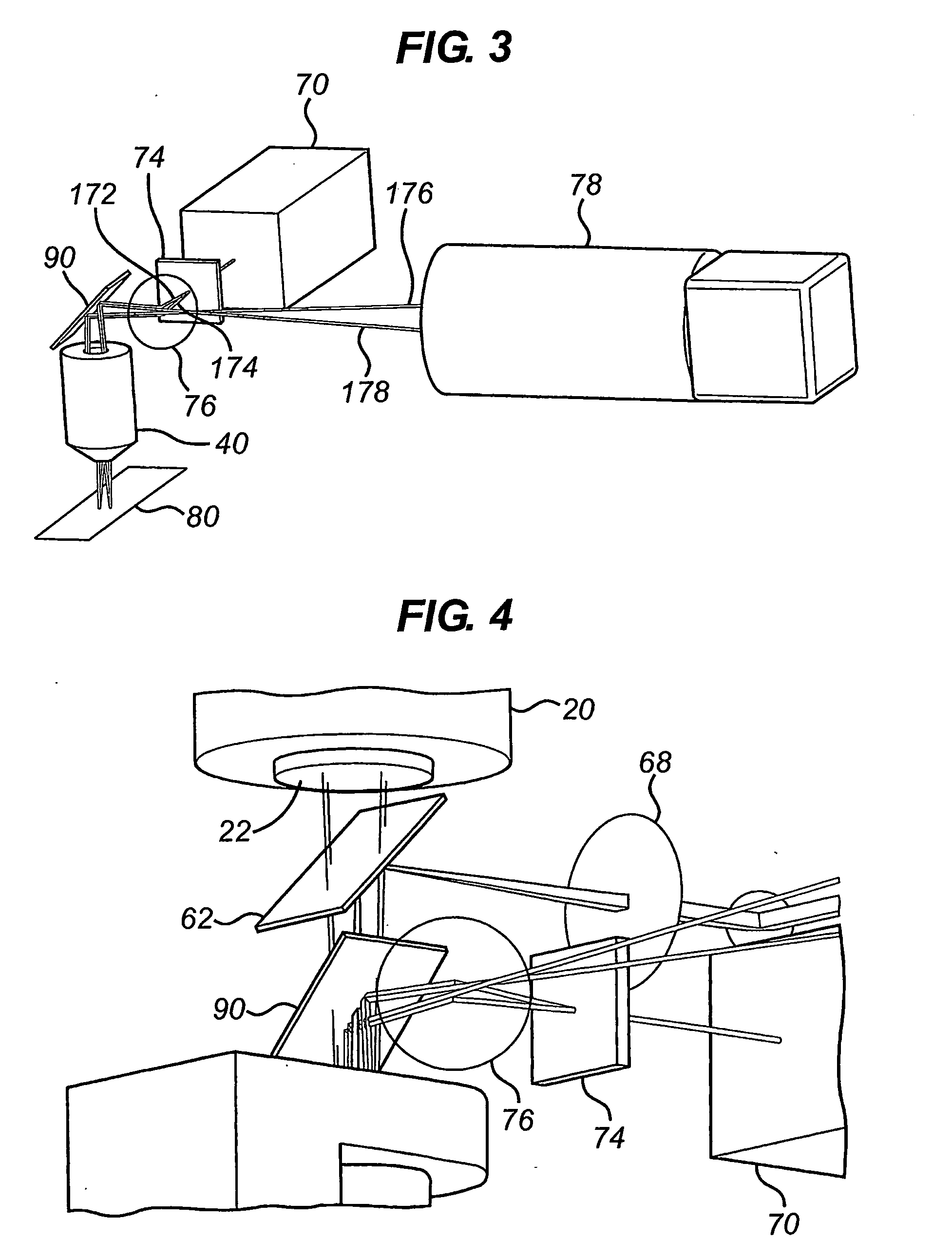
[0095]As can be seen from FIG. 2, the auto-focus mechanism 70 uses a sepa...


PUM

PropertyMeasurementUnit
depth of fieldaaaaaaaaaa
areaaaaaaaaaaa
thicknessaaaaaaaaaa

Abstract

The present invention relates to apparatus for the imaging of single molecules.

Description

[0001]All documents and on-line information cited herein are incorporated by reference in their entirety.TECHNICAL FIELD[0002]The present invention relates to apparatus for the imaging of single molecules.BACKGROUND ART[0003]Imaging apparatus and methods are used worldwide to obtain images of a sample which is to be analysed. This is often done by focusing on small areas of the sample and combining images of these small areas to obtain a single detailed image of the whole or a larger part of the sample. Some of these imaging techniques use single dye molecule spectroscopy, single quantum dot spectroscopy, and related types of ultra-sensitive microscopy and spectroscopy. However, there are few approaches that apply these techniques to microarray analysis.[0004]Microarray experiments generally involve fluorescent microscopy of a sample that adheres to the surface of a microscope slide. There are different types of experimental designs, and the most common method images the emission of...

Claims


Application Information

Patent Timeline
Patent Type & Authority Applications(United States)
IPC IPC(8): G01N21/64G02B21/02G02B21/26
CPCG02B21/245G02B21/16
Inventor LUEERSSEN, DIETRICH WILHELM KARL
Owner OXFORD GENE TECH IP
Learn More