Eureka AIR delivers breakthrough ideas for toughest innovation challenges, trusted by R&D personnel around the world.

Hip protector implant

a technology of hip protector and implant, which is applied in the field of implants, can solve the problems of reducing fracture risk and reducing energy transfer to the proximal, and achieve the effects of reducing peak pressure and peak stress, reducing fracture risk, and increasing the contact area involved in impa

Inactive Publication Date: 2010-01-21
SMIT ARNO
View PDF11 Cites 10 Cited by
  • Summary
  • Abstract
  • Description
  • Claims
  • Application Information

AI Technical Summary

Benefits of technology

[0010]The implant system according to the invention provides a method of decreasing fracture risk by reducing the concentration of forces on the lateral aspect of the greater trochanter of the femur at the time of a fall. This is achieved by increasing the contact area involved in the impact of a fall. This measure alone reduces peak pressures and peak stresses to the lateral aspect of the femur. In addition, the implants according to the invention allow absorption of energy, through the selection of implant material, such that elastic and / or plastic deformation can occur; or through energy dissipation to the soft tissues between the implant and the lateral aspect of the femur. The end result of the implant is a decrease in energy transfer to the proximal femur, and the spread of such energy over a greater volume of bone, with resultant decreased fracture risk. The implant is surgically implanted so that patients will not be left unprotected because of their failure to comply with instructions.
[0011]The implants may be coupled with an implant system for mechanical re-enforcement of bone, utilizing a load-sharing device, to minimize stress shielding over a long time frame. Alternatively, the implant system for mechanical re-enforcement of bone can be used on its own merits, decreasing fracture risk by strengthening the area of proximal femur.
[0012]The implants according to the invention provide enforcement of the area at risk for fracture, using implants designed to avoid excessive stress shielding of the surrounding bone. This is achieved through use of a compliant, flexible material so that the implant is similar in stiffness to the surrounding bone. In essence, the implant is only fully loaded at the time of excessive impact, when fracture could occur. By ensuring ongoing loading of the surrounding bone, progressive bone loss due to stress shielding can be minimized or avoided. In addition, a flexible implant is less likely to cut out of soft bone, when fully loaded.
[0013]The implants can be placed with minimally invasive surgery. Bone preparation through placement of drill holes, etc. is not necessary or is greatly reduced with the implants designed to purely decrease the peak pressures and stresses, and to minimize energy transfer. If fracture surgery is necessary, the presence of the prophylactic implant should not pose significant difficulties for the treating surgeon. If a fracture should occur with an implant in situ, the implant should have sufficient strength and stiffness to minimize the risk of displacement, disruption of the blood supply to the femoral head, and fracture bleeding. In this way, the likelihood is increased that the fracture can heal without formal fracture surgery, thus avoiding the significant risks associated with fracture surgery.

Problems solved by technology

The end result of the implant is a decrease in energy transfer to the proximal femur, and the spread of such energy over a greater volume of bone, with resultant decreased fracture risk.

Method used


Image

  • Hip protector implant
  • Hip protector implant
  • Hip protector implant

Examples


Embodiment Construction

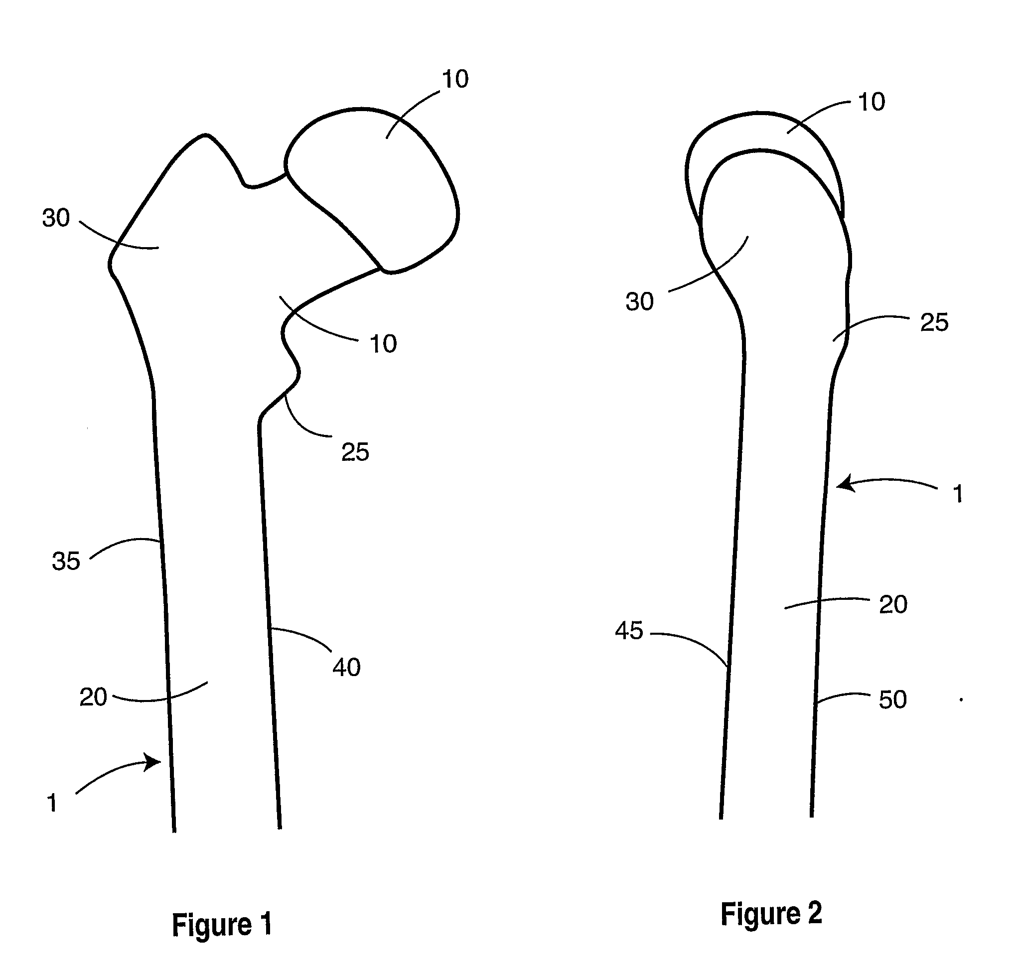
[0072]FIGS. 1 through 3 provide views of proximal femur 1. Components of the femur, as seen in FIGS. 1 through 3, include femoral head 10, femoral neck 15, femoral shaft 20, lesser trochanter 25, greater trochanter 30, medial femoral cortex 35, lateral femoral cortex 40, anterior femoral cortex 45, and posterior femoral cortex 50. Blood supply 55 runs from femoral neck 15 to femoral head 10.

[0073]FIGS. 4 and 5 show typical fractures that may occur in the femur. Femoral neck fracture 60 occurs in femoral neck 15. Intertrochanteric fracture 65 occurs in the lesser trochanter 25 or greater trochanter 30. Subtrochanteric fracture 70 occurs below lesser trochanter 25. In a typical fall area 75 absorbs the direct impact.

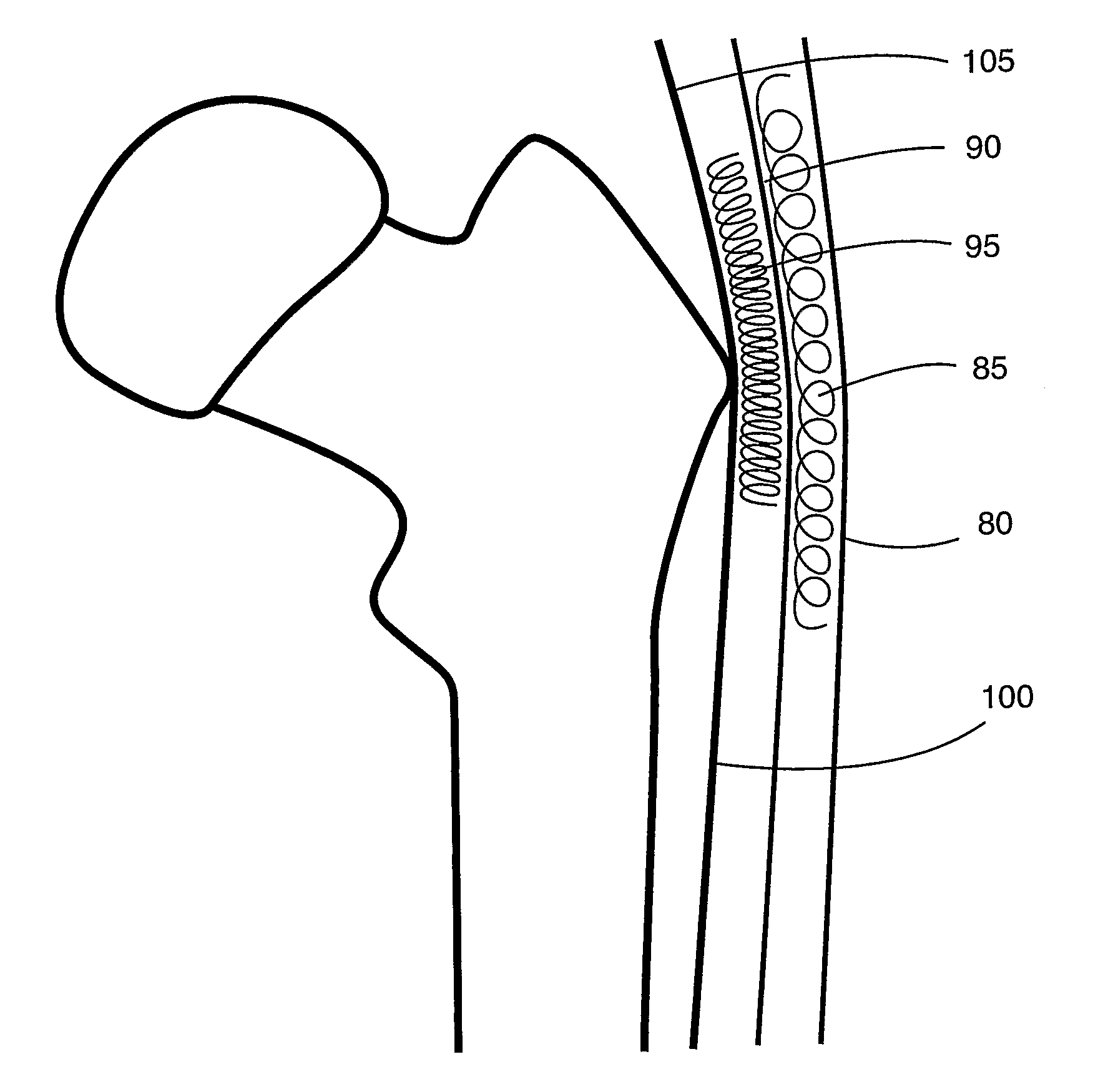
[0074]FIG. 6 shows the soft tissue surrounding the femur. Skin 80 forms an outer layer. Subcutaneous soft tissue 85 is beneath skin 80. Fascia lata 90 and bursa 95 are also within the soft tissue. The abductor insertion point 105 and point of origin of the vastus lateralis...


PUM


Abstract

An implant system is described to decrease the risk of hip fracture in humans determined to be at increased risk for hip fracture, over a time span well over several years after implantation. This implant increases the size of the contact area on the proximal femur at the time of a fall, decreasing contact pressures and contact stresses. The implant may be able to absorb energy on impact or cause an increase of energy absorption by the soft tissues, thus decreasing the energy transfer to the proximal femur at the time of a fall. The implant may also strengthen the proximal femur, while minimizing stress shielding of the surrounding bone. In addition, it minimizes the risk of displacement should fracture occur, thus minimizing the risk of formal fracture surgery. The method of application minimizes risks associated with initial application of the implant.

Description

[0001]This application claims the benefit of U.S. Patent Application No. 60 / 791,471, which is hereby incorporated by reference.FIELD OF THE INVENTION[0002]The invention relates to implants for preventing bone fractures, and more particularly for preventing hip fractures.BACKGROUND OF THE INVENTION[0003]Low to moderate energy fractures of the hip, such as those caused by a fall from a standing or sitting position, pose a significant clinical and social problem. The majority of these fractures occur among the elderly, although there are additional risk groups, such as patients with underlying primary bone disorders, e.g. osteomalacia or osteogenesis imperfecta; patients with neurological disorders, either through increased fall risk, e.g. Parkinson's disease, or through secondary bone disorders, e.g. disuse osteopenia associated with paraplegia; or patients with osteomalacia as a result of the use of certain pharmacological agents, e.g. anticonvulsants. It is estimated that among the ...

Claims


Application Information

Patent Timeline
Patent Type & Authority Applications(United States)
IPC IPC(8): A61F2/32
CPCA61B17/742A61B17/8061A61B17/746
Inventor SMIT, ARNO
Owner SMIT ARNO
Why Eureka
Eureka Blog
Learn More