Composite particles for electrochemical element electrode

a technology of electrochemical elements and composite particles, applied in the field of composite particles, can solve the problems of difficult to obtain electrode sheets stably and continuously, particle formability is inferior, etc., and achieve the effect of large electric capacitance and low internal resistan

Active Publication Date: 2009-12-31
ZEON CORP
View PDF7 Cites 16 Cited by
  • Summary
  • Abstract
  • Description
  • Claims
  • Application Information

AI Technical Summary

Benefits of technology

[0021]Composite particles for electrochemical element electrodes according to the present invention have a structure where an electrode active material and an electric conductive material (mainly electric conductive material) whose weight average particle diameter is comparatively small are distributed in the outer layer portion (outer shell portion), and an electrode active material and an electric conductive material (mainly electrode active material) whose weight average particle diameter is comparatively large are distributed in the inner layer portion (core portion). In the electrode obtained using this composite particle, the internal resistance becomes low. Moreover, the core portion is occupied by particles having a large particle diameter, and accordingly, a lot of fine pores are distributed, and it has a structure where electrolysis solution permeates easily, and large electric capacitance can be obtained. Further, the electrode for electrochemical elements obtained using the electrochemical element electrode material comprising the composite particles can be used for electrochemical elements which can perform storage and conversion of energy.

Problems solved by technology

However, the composite particles have inferior formability, and accordingly, it has been difficult to obtain electrode sheets stably and continuously.

Method used


Image

  • Composite particles for electrochemical element electrode
  • Composite particles for electrochemical element electrode
  • Composite particles for electrochemical element electrode

Examples


example 1

[0083]100 parts of electrode active material (activated carbon having specific surface area of 2000 m2 / g and weight average particle diameter of 5 μm), 5 parts of electric conductive material (acetylene black “Denka Black Powder”: manufactured by Denki Kagaku Kogyo K.K.), 7.5 parts of dispersible binder (aqueous dispersion of cross-linked acrylate polymer with average particle diameter of 0.15 μm, and glass transition temperature of −40° C.: “AD211”: manufactured by Zeon Corporation), 93.3 parts of soluble resin (1.5% aqueous solution of carboxymethyl cellulose “ON-800H”: manufactured by Daicel Chemical. Industries, Ltd.), and 341.3 parts of ion exchanged water were stirred and mixed by a TK homomixer to obtain slurry having solid content of 20%. Subsequently, the slurry was charged into a hopper 51 of a spray drier (with a pin type atomizer, manufactured by Ohkawara Kakohki Co. Ltd.) as shown in FIG. 5, and sent to the top nozzle 57 with pump 52, and sprayed from the nozzle into th...

example 2

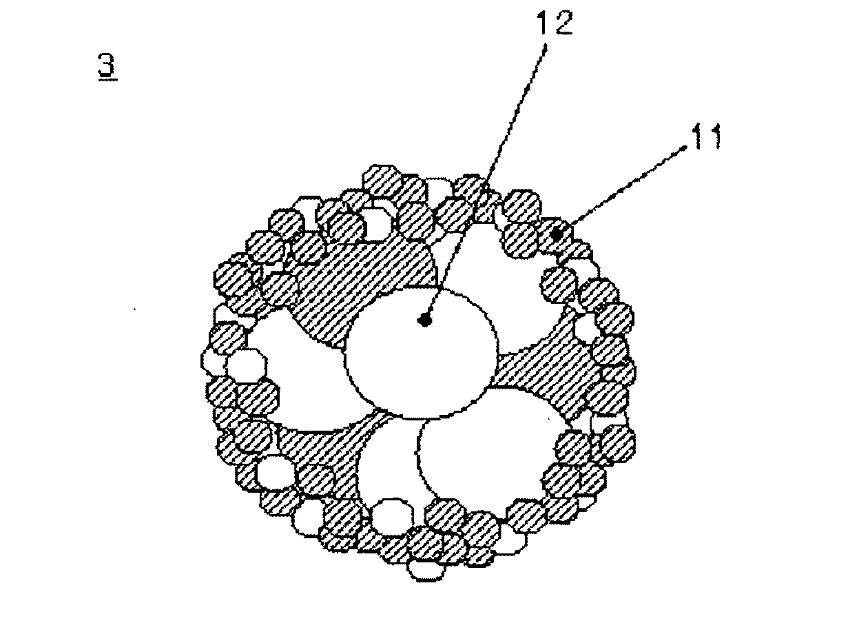
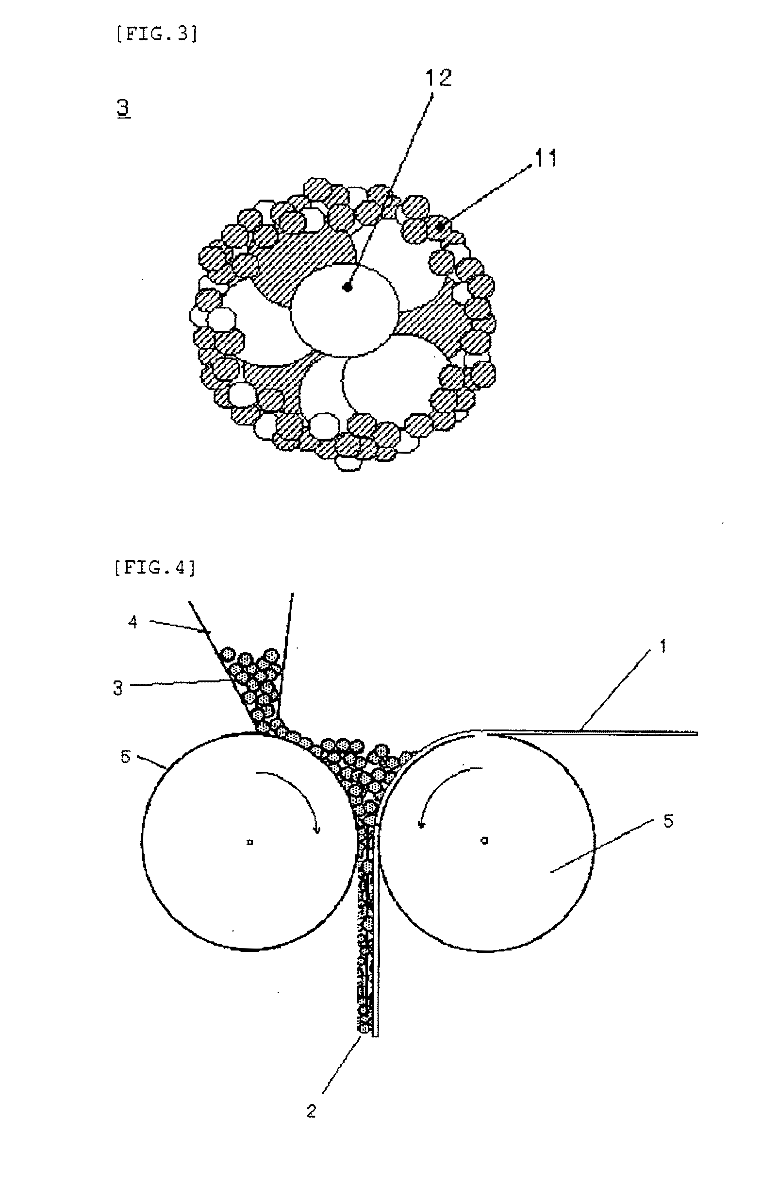
[0085]Slurry was obtained in the same manner as in the Example 1 except that 5.6 parts of polytetrafluoroethylene were used in the place of the binder (AD-211) used in the Example 1, and by use of this slurry, a spherical composite particle A-2 of particle diameter 5 μm to 70 μm (average particle diameter of 50 μm) was obtained. The composite particle A-2 consisted of a core portion and an outer shell portion in the same manner as the composite particle A-1, and the weight average particle diameter of the electrode active material and the electric conductive material which form the outer shell portion, was smaller than the weight average particle diameter of the electrode active material and the electric conductive material which form the core portion, and had the same structure as that of the particles as shown in FIG. 3.

[0086]The obtained composite particle was rolled and formed by use of the roll pressing machine in the same manner in the Example 1, and an electrode sheet having ...

example 3

[0087]Slurry S1 (solid content 8%) made of 2 parts ot an electric conductive material (Denka Black Powder: manufactured by Denki Kagaku Kogyo), 7.5parts (solid content 40%) of a binder (AD211: manufactured by Zeon Corporation), 3.33 parts (solid content 4%) of carboxymethyl cellulose (“DN-10L” manutacturedby Daicel Chemical Industries, Ltd.), 17.76 parts (solid content 1.5%) of carboxymethyl cellulose (“DN-800H” manufactured by Daicel Chemical Industries, Ltd.), and 36.9 parts of ion exchanged water was prepared.

[0088]100 parts of an electrode active material (activated carbon having specific surface area of 2000 m2 / g and weight average particle diameter of 5 μm) was charged into an Agglomaster manufactured by Hosokawa Micron Corp., and it was fluidized by 80° C. hot wind, and the above slurry 31 was atomized into the Agglomaster, and fluidized-granulation was performed to give a particle A. The average particle diameter of the particle A was 40 μm.

[0089]Slurry S2 (solid content 10....


PUM

PropertyMeasurementUnit
specific surface areaaaaaaaaaaa
particle diameter distributionaaaaaaaaaa

Abstract

The present invention provides a method of producing composite particle for high density electrochemical element electrodes in electrochemical elements having low internal resistance and high capacitance.Slurry containing an electric conductive material and a binder is obtained, and the slurry is sprayed to a fluidized electrode active material to carry out fluidized-granulation, and further particles obtained by the fluidized-granulation are rolling-fluidized granulated, and thereby, composite particle for electrochemical element electrode, containing electrode active materials, electric conductive materials, and binders, and being structured of an outer layer portion (outer shell portion) and an inner layer portion (core portion), where the outer shell portion and the core portion are made by bonding the electrode active material and the electric conductive material by the binder, and the weight average particle diameter of the electrode active material and the electric conductive material which form the outer shell portion is smaller than the weight average particle diameter of the electrode active material and the electric conductive material which form the core portion are obtained.

Description

TECHNICAL FIELD[0001]The present invention relates to composite particles which constitute an electrode material used preferably for electrochemical elements such as a lithium ion secondary battery and an electric double layer capacitor, in particular an electric double layer capacitor (in the present specification, referred to simply as “composite particles”) Further, the present invention relates to an electrode material comprising the composite particles, and an electrochemical element electrode using the electrode material.BACKGROUND ART[0002]Electrochemical elements such as a lithium ion secondary battery and an electric double layer capacitor have advantageous characteristics that they are small, lightweight, their energy density is high, and they can be repeatedly charged and discharged, and accordingly their demand is expanding rapidly. The lithium ion secondary battery has a relatively large energy density, and it is used in the fields such as cellular phones and notebook p...

Claims


Application Information

Patent Timeline
Patent Type & Authority Applications(United States)
IPC IPC(8): H01M4/62H01B1/00H01B1/04H01G9/00H01G11/22H01G11/42H01M4/02H01M4/04H01M4/13H01M4/139H01M4/36H01M10/0525H01M10/36
CPCH01G11/38Y10T29/49108H01M4/02H01M4/04H01M4/13H01M4/139H01M4/364H01M4/621H01M4/624H01M10/0525H01M2004/021Y02E60/122Y02T10/7011Y02T10/7022Y02E60/13H01G11/42Y02T10/70Y02E60/10H01M4/58H01M4/62H01M10/05
Inventor TSUCHIYA, FUMIAKIFUKUMINE, MAYUMI
Owner ZEON CORP
Why Eureka
Try Eureka