
Battery

a battery and battery technology, applied in the field of batteries, can solve the problems of increasing internal resistance and reducing battery volume efficiency, and achieve the effect of increasing battery volume efficiency and reducing internal resistan

Inactive Publication Date: 2004-02-05
SANYO ELECTRIC CO LTD
View PDF2 Cites 65 Cited by
  • Summary
  • Abstract
  • Description
  • Claims
  • Application Information

AI Technical Summary

Benefits of technology

The present invention provides a battery with reduced internal resistance and increased battery efficiency. This is achieved by reducing the length of the current path from the electrode unit to the terminal assembly and increasing the negative electrode current collector plate. The battery includes a current collector plate connected to the negative electrode unit through a negative electrode terminal assembly. The current collector plate has connecting pieces welded to the base of the terminal assembly, reducing the length of the current path and minimizing electrical resistance. The battery also includes a flange portion attached to the inner or outer circumferential wall of the connecting piece or pieces, which reduces deadspace in the battery can. Overall, the present invention provides a more efficient and compact battery design.

Problems solved by technology

The long current path increases internal resistance and decreases battery volume efficiency.

Method used


Image

  • Battery
  • Battery
  • Battery

Examples


Embodiment Construction

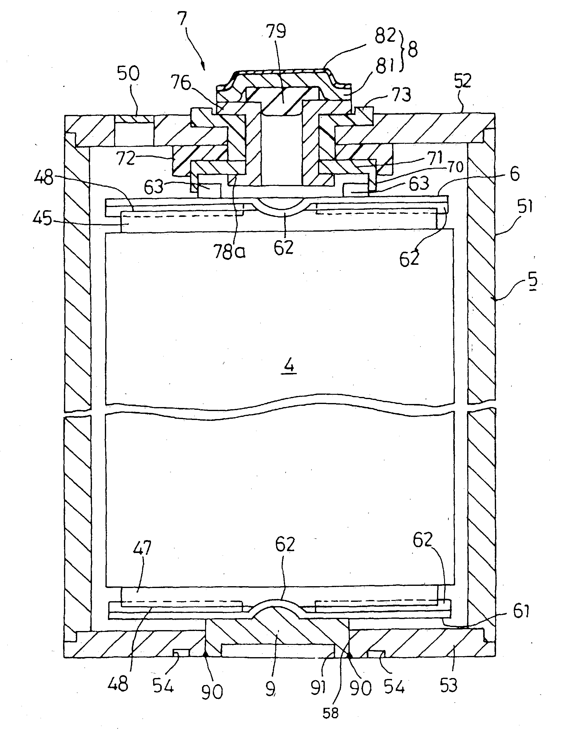
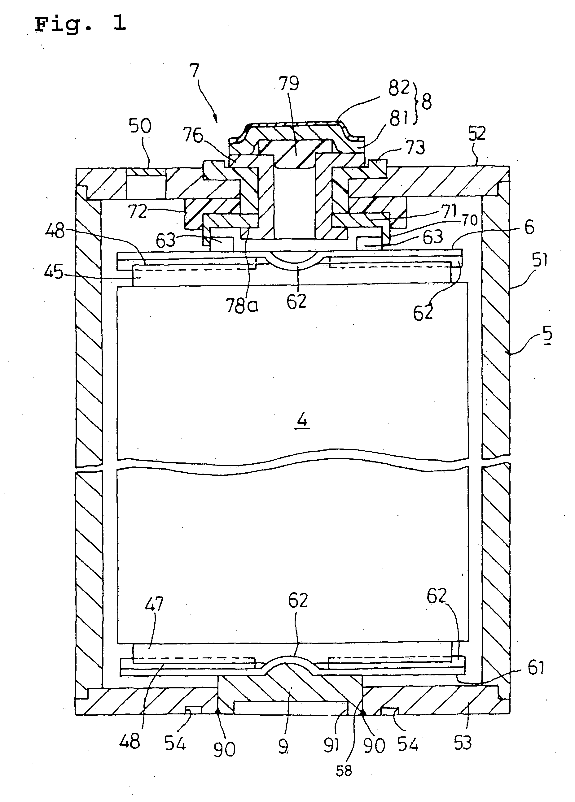
[0071] In the present invention, one or more connecting pieces protrusively formed on a current collector plate is directly welded to the base portion of the terminal assembly to electrically connect the electrode unit and the terminal assembly so that the length of current path from the electrode unit to the terminal assembly is shortened as compared to a conventional tab connection and electrical resistance in the path becomes extremely low.

[0072] Direct welding of the current collector plate by way of the one or more connecting pieces to the base portion of the terminal assembly reduces deadspace in the battery can.

[0073] A flange portion (70) to be attached to an inner or outer circumferential wall of a connecting piece or pieces (63) is formed on and projects from the base portion of the terminal assembly and the flange portion (70) is welded to the connecting piece or pieces (63) by laser beam welding.

[0074] According to an embodiment of the present invention, the flange porti...


PUM

PropertyMeasurementUnit
thicknessaaaaaaaaaa
thicknessaaaaaaaaaa
energy densityaaaaaaaaaa

Abstract

A battery including an electrode unit housed in a battery can and which generates electricity which can be taken out of the battery via a pair of negative and positive electrode terminals, wherein a terminal assembly is installed in the battery, a current collector plate is connected to an edge of an electrode of the electrode unit for connecting the electrode unit to the terminal assembly, and one or more than one connecting piece which is protrusively formed on a surface of the current collector plate is welded and secured to a base portion of the terminal assembly.

Description

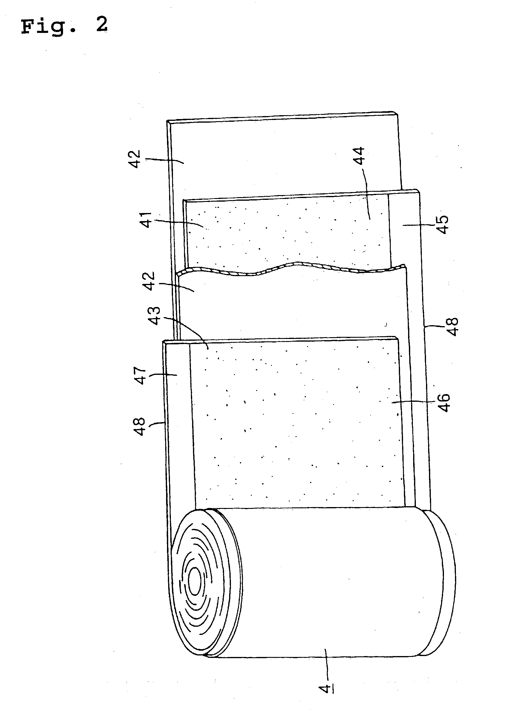
[0001] The present invention relates to a battery such as a lithium ion secondary battery in which an electrode unit which is an electricity generating element is housed in a battery can, and electricity generated by the electrode can be taken out from the can.[0002] A lithium ion secondary battery having a high energy density has recently received attention as a power source for portable electronic equipment, electric vehicles, and the like. A cylindrical lithium ion secondary battery, as shown in FIG. 13, includes a spirally wound, or rolled-up, electrode unit (2) housed in a positive electrode can (1), and a sealing plate (11) fixed on an opening of the positive electrode can (1). An insulator (12) is placed between the positive electrode can (1) and the sealing plate (11). A negative electrode terminal (13) having a built-in gas vent valve (164) is connected to the sealing plate (11).[0003] The spirally wound electrode (2) comprises a negative electrode (21), separator (22) and ...

Claims


Application Information

Patent Timeline
Patent Type & Authority Applications(United States)
IPC IPC(8): H01M10/05H01M50/538H01M50/548H01M50/553H01M50/562H01M50/566
CPCH01M2/022H01M2/263Y02E60/122H01M10/0525H01M10/0587H01M2/30Y02E60/10H01M50/107H01M50/538H01M50/553H01M50/548H01M50/562H01M50/566
Inventor NAKANISHI, NAOYASATOH, KOUICHIFUNAHASHI, ATSUHIRONOHMA, TOSHIYUKIYAMAUCHI, YASUHIROMIYAZAKI, NORIYUKI
Owner SANYO ELECTRIC CO LTD
Learn More