X-ray imaging photostimulable phosphor screen or panel

a phosphor screen or phosphor technology, applied in the field of radiography, can solve the problems of slow x-ray degradation, sensitivity to oxidation of divalent eu, degradation of alkali halide salt phosphors and scintillators, etc., and achieve the effects of improving radiation hardness, high divalent europium dopant level, and high speed

Inactive Publication Date: 2009-10-01
T2PHARMA GMBH
View PDF29 Cites 1 Cited by
  • Summary
  • Abstract
  • Description
  • Claims
  • Application Information

AI Technical Summary

Benefits of technology

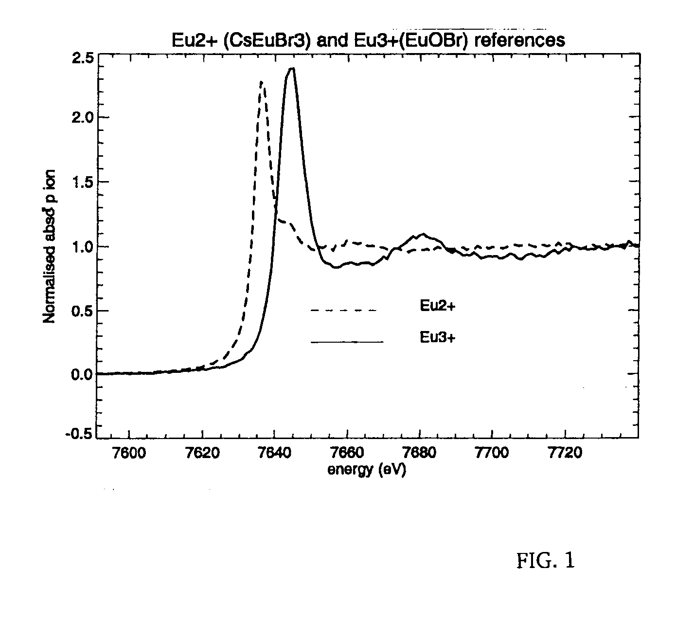
[0011]As an advantageous effect, more in particular for storage phosphor plates, prepared from CsEuBr3 as Europium dopant precursor in the preparation of photostimulable CsBr:Eu phosphor plates, an improved radiation hardness is encountered, while maintaining a high level of divalent Europium dopant on top of the needles during a long exposure time with soft X-rays, if compared with storage phosphor plates, prepared from EuOBr as Europium dopant precursor, even in humidity conditions of up to about 90%. Such effects are advantageously applied, at least in mammographic applications with low exposure doses from X-rays having an energy in the range from 28 to 35 keV, wherein a high speed and maintained stability is required after frequent re-use of said storage phosphor plates in diagnostic imaging.

Problems solved by technology

Besides problems with respect to radiation hardness, alkali halide salt phosphors and scintillators suffer from degradation by moisture, as being very sensitive thereto.
Moreover sensitivity to oxidation of divalent Eu is another weakness, besides the slow X-ray degradation.

Method used


Image

  • X-ray imaging photostimulable phosphor screen or panel
  • X-ray imaging photostimulable phosphor screen or panel

Examples


examples

[0034]While the present invention will hereinafter be described in connection with preferred embodiments thereof, it will be understood that it is not intended to limit the invention to those embodiments.

[0035]Comparative Storage Plate CB75022

[0036]A CsBr:Eu photostimulable phosphor screen having a flexible anodized aluminum was prepared in a vacuum chamber by means of a thermal vapor deposition process, starting from a mixture of CsBr and EuOBr as raw materials.

[0037]Said deposition process onto said flexible anodized aluminum support was performed in such a way that said support was rotating so that the momentary magnitude of the velocity was constant over its whole area. An electrically heated oven and a refractory tray or boat in which 750 g of a mixture of CsBr and EuOBr as raw materials in a 99.5% / 0.5% CsBr / EuOBr percentage ratio by weight were present to become vaporized. The crucible was an elongated boat having a length of 175 mm, a width of 48 mm and a height of 60 mm comp...


PUM

PropertyMeasurementUnit
energyaaaaaaaaaa
temperatureaaaaaaaaaa

Abstract

In a method of preparing a phosphor or scintillator layer to become deposited on a support, a vapor depositing step is applied from a crucible unit by heating as phosphor precursor raw materials present in said crucible, a Cs(X,X′) matrix compound and an activator or dopant precursor compound, wherein said crucible unit comprises at least a bottom and surrounding side walls as a container for phosphor precursor raw materials present in said crucible in liquefied form after heating said crucible, and wherein said Cs(X,X′) matrix compound has a higher vapor pressure than said activator or dopant precursor compound, said method comprising a step of providing said activator or dopant compound in form of a precursor raw material represented by the formula CsxEuyX′(x+αy), wherein x, y and α are integers, wherein x / y is more than 0.25 and wherein α is at least 2, wherein X represents Br and wherein X′ stands for F, Cl, Br, I or a combination thereof; followed by an annealing step after a vapor depositing step, provided that said annealing step proceeds in an ambient atmosphere after cooling said phosphor or scintillator layer, deposited on said support; and wherein as a result a binderless needle-shaped Cs(X,X′):Eu phosphor or scintillator layer becomes provided, having on top of its needle-shaped phosphors, aligned in parallel, an average ratio of divalent to trivalent europium dopant of more than 1:1; wherein said average ratio decreases to an extent of less than 2% per hour, while being exposed to X-rays having an energy in the range from 1 to 100 keV.

Description

CROSS-REFERENCE TO RELATED PATENT APPLICATIONS[0001]This application claims the benefit of U.S. Provisional Application No. 61 / 012,609 filed Dec. 10, 2007, which is incorporated by reference. In addition, this application claims the benefit of European Patent Application No. 07122464.6 filed Dec. 6, 2007, which is also incorporated by reference.DESCRIPTION[0002]1. Field of the Invention[0003]The present invention relates to radiography and, more in particular, to an X-ray imaging photostimulable phosphor screen or panel, useful in radiation applications as e.g. mammography.[0004]2. Background of the Invention[0005]In study results on the radiation damage of the storage phosphor CsBr:Eu2+ as reported by Jorg Zimmermann, Technical University of Darmstadt, Germany, in Journal of Luminescence, 114 (2005), p. 24-30, it has been shown that a high X-ray dose causes a significant deterioration of the photostimulated luminescence (PSL) accompanied by a degradation of the UV-excited Eu2+-fluo...

Claims


Application Information

Patent Timeline
Patent Type & Authority Applications(United States)
IPC IPC(8): C09K11/77C23C16/00
CPCG21K4/00C09K11/7733
Inventor TAHON, JEAN-PIERRELENAERTS, JENSVINCZE, LASZLOSILVERSMIT, GEERTLEBLANS, PAUL
Owner T2PHARMA GMBH
Why Eureka
Try Eureka