
Information processing apparatus and control method thereof

Inactive Publication Date: 2009-09-17
CANON KK
View PDF5 Cites 29 Cited by
  • Summary
  • Abstract
  • Description
  • Claims
  • Application Information

AI Technical Summary

Benefits of technology

[0009]The present invention enables realization of an information processing apparatus that is provided with a volatile first storage unit and a nonvolatile second storage unit, and that reduces power supply to the second storage u

Problems solved by technology

In the case of a general-purpose OS having a demand paging function of only allocating memory pages that have been accessed to physical memory, for example, anticipating when the text area of an executable file or a library will be loaded from a file can be difficult.
Also, in the case of a general-purpose OS having a swap function of saving data that does not fit in memory to hard disk, anticipating the swap in and swap out timing can be difficult.
Further, while many open source applications can generally be used with a general-purpose OS, completely ascertaining and regulating the file access timing of these applications can be difficult.
Thus, in an information processing apparatus employing a general-purpose OS, power supply to nonvolatile memory cannot be reduced even when operating in power saving mode.

Method used


Image

  • Information processing apparatus and control method thereof
  • Information processing apparatus and control method thereof
  • Information processing apparatus and control method thereof

Examples


first embodiment

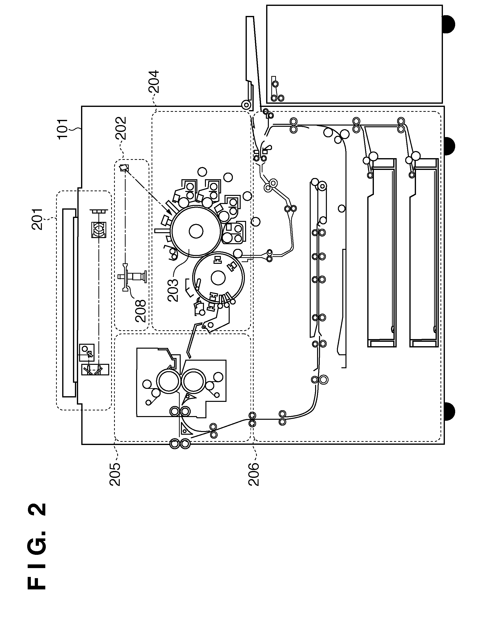
[0046]Next, the configuration of the MFP 101 will be described with reference to FIG. 2. FIG. 2 shows an exemplary hardware configuration of the MFP 101 according to the The MFP 101 according to the present embodiment is capable of color printing and is constituted by a scanner unit 201, a laser exposure unit 202, a photosensitive drum 203, an image forming unit 204, a fixing unit 205, a feed / conveyance unit 206, and a printer controller (not shown) for controlling these components.

[0047]The scanner unit 201 optically reads an original image by illuminating an original placed on an original platen, and converts the image to an electrical signal to create image data. The laser exposure unit 202 causes a light beam such as laser light modulated according to the image data to be incident a rotating polygon mirror 208 that rotates at an equiangular velocity and irradiate the photosensitive drum 203 as reflected scanning light.

[0048]The image forming unit 204 rotationally drives the pho...

second embodiment

[0113]First, a method of reducing the volume of copying and flushing in the swap storage area will be described with reference to FIG. 19. FIG. 19 illustrates a memory management table according to the The memory management table shown in FIG. 19 is managed by the OS illustrated in FIG. 11.

[0114]Reference numeral 1901 denotes the memory management table in a normal state (normal operating mode). Reference numeral 1902 denotes the memory management table after transitioning to power saving mode. Reference numeral 1903 denotes the memory management table in the case where a swap in / out has occurred in power saving mode. Reference numeral 1904 denotes the memory management table after having transitioned from power saving mode to normal operating mode. Here, three processes (process IDs: 25, 26, 27) are given as an example, with the process IDs of the processes required in power saving mode being 25 and 26.

[0115]When transitioning to power saving mode, the MFP controller 302 first sav...

third embodiment

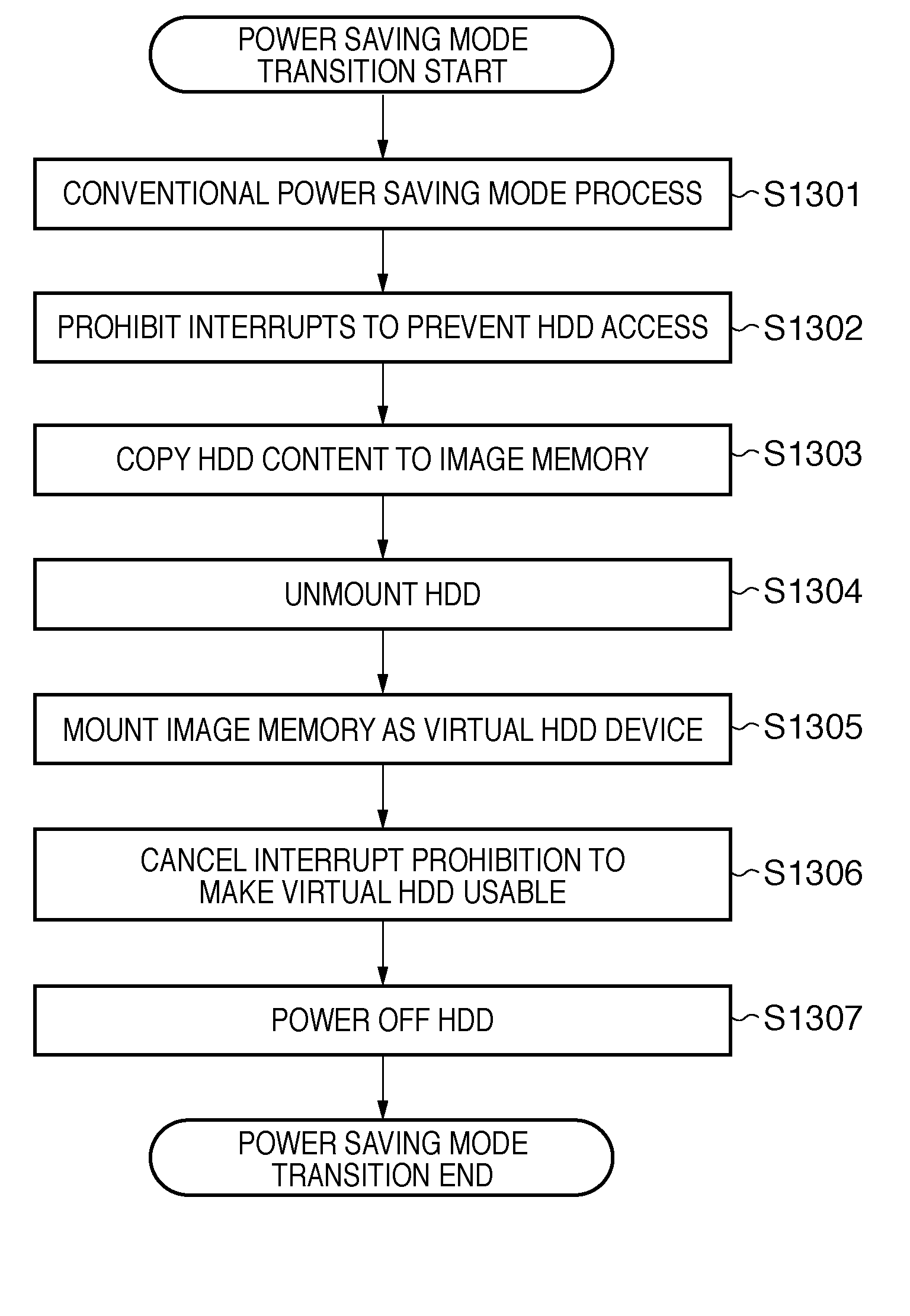
[0121]FIG. 22 is a flowchart showing a processing procedure for transitioning to power saving mode according to the The processing described hereinafter is mainly performed under the overall control of the MFP controller 302. According to the present embodiment, an image work area of memory is used as a RAM disk when transitioning to power saving mode, and data on the hard disk drive 313 is transferred to the RAM disk area. Further, if data on the hard disk drive 313 is required as a result of an interrupt from a network or the like, supplying power to the hard disk drive 313 is made unnecessary by accessing the data transferred to the RAM disk.

[0122]First, in step S2201, the MFP 101 starts the process of transitioning to power saving mode in accordance with a factor such as a timer or a user instruction. Once the MFP 101 has transitioned to power saving mode, there will be areas of the main storage device such as the image work area that are not being used. In step S2202, the MFP ...


PUM


Abstract

An information processing apparatus used to reduce power supply to nonvolatile memory when in power saving mode. To accomplish this, the information processing apparatus stores data in the nonvolatile memory that can be used in power saving mode to a volatile memory to which power will still be supplied while in power saving mode. Further, the information processing apparatus enables the operating system to recognize the storage area in which the data is stored as a replacement for the nonvolatile memory.

Description

BACKGROUND OF THE INVENTION[0001]1. Field of the Invention[0002]The present invention relates to an information processing apparatus that has a plurality of operating modes including a power saving mode and to a control method thereof.[0003]2. Description of the Related Art[0004]With regard to power saving in an information processing apparatus, measures are being considered for suppressing power consumption by reducing power supply to hardware not being used when the information processing apparatus is idle. An operating mode in which power consumption is decreased relative to normal operation is called a power saving mode.[0005]For example, Japanese Patent Application[0006]Laid-Open No. 2004-074621 proposes a technique of reducing power supply to nonvolatile memory such as the hard disk of an information processing apparatus in power saving mode, in order to reduce power consumed by nonvolatile memory.[0007]Recent information processing apparatuses have started employing a general...

Claims


Application Information

Patent Timeline
IPC IPC(8): G06F1/00G06F12/00G06F13/00
CPCG03G15/5004G06F1/3203G06F1/3268H04N1/00885H04N1/00891Y02B60/32H04N1/32358H04N2201/0094H04N2201/3288H04N2201/3295Y02B60/1246H04N1/00904Y02D10/00Y02D30/50
Inventor KOSHIKA, TAKASHIHIGASHI, HIDENORI
Owner CANON KK
Learn More