Eureka AIR delivers breakthrough ideas for toughest innovation challenges, trusted by R&D personnel around the world.

Full-rotation hydraulic inward-pushing-type high-build-up-rate rotation guide tool

A technology of rotary steering and build rate, which is used in directional drilling, drilling equipment, drilling equipment and methods, etc., can solve the problem of high strength requirements of upper drilling tools metal materials, alternating fatigue damage of upper drilling tools, and aggravating upper drill string bending. Stress and other problems, to achieve the effect of simplifying the power supply system, reducing the stress and improving the working life

Active Publication Date: 2018-12-18
INST OF GEOLOGY & GEOPHYSICS CHINESE ACAD OF SCI
View PDF5 Cites 18 Cited by
  • Summary
  • Abstract
  • Description
  • Claims
  • Application Information

AI Technical Summary

Problems solved by technology

[0005] 1) Three sets of highly integrated motor-pump-hydraulic module assemblies with independent control are used, which are expensive and the cost of later maintenance is also high
[0006] 2) The bending of the upper part of the rotary steerable tool consumes the pushing force, and at the same time, the bending caused by the pushing force increases the bending stress of the upper drill string. The strength requirements are high, and the pusher pushes against the well wall, resulting in high wear and tear;
[0007] 3) The rotating guide tool is set without rotating the jacket, and the guide tool is not easy to realize the back-cutting operation and there is a risk of drill sticking;
[0009] 5) The disc valve used for flow distribution is a normally open structure, and the rotary guiding tool pushes against the palm and still pushes back and forth against the well wall to work in the process of not needing guidance, resulting in a lower life of the piston seal

Method used


Image

  • Full-rotation hydraulic inward-pushing-type high-build-up-rate rotation guide tool
  • Full-rotation hydraulic inward-pushing-type high-build-up-rate rotation guide tool
  • Full-rotation hydraulic inward-pushing-type high-build-up-rate rotation guide tool

Examples


Embodiment Construction

[0051] In order to make the object, technical solution and advantages of the present invention clearer, the present invention will be further described in detail below in conjunction with the accompanying drawings and embodiments. It should be understood that the specific embodiments described here are only used to explain the present invention, not to limit the present invention.

[0052] On the contrary, the invention covers any alternatives, modifications, equivalent methods and schemes within the spirit and scope of the invention as defined by the claims. Further, in order to make the public have a better understanding of the present invention, some specific details are described in detail in the detailed description of the present invention below. The present invention can be fully understood by those skilled in the art without the description of these detailed parts.

[0053] In the prior art, taking the Baker Hughes AutoTrak Curve rotary steerable tool as an example, t...


PUM


Abstract

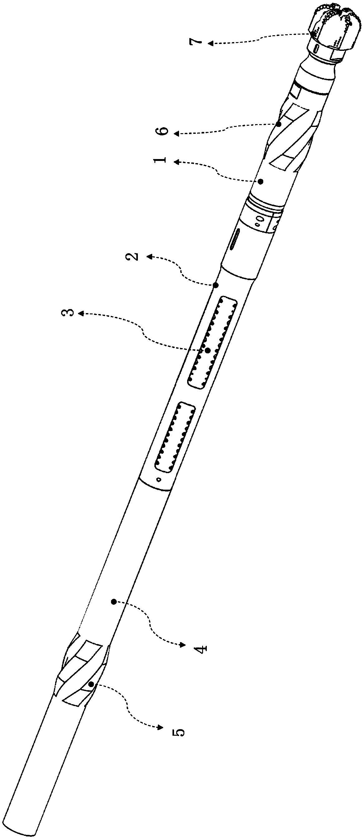
The invention mainly belongs to the technical field of rotary guide systems, and particularly relates to a full-rotation hydraulic inward-pushing-type high-build-up-rate rotation guide tool. The full-rotation hydraulic inward-pushing-type high-build-up-rate rotation guide tool adopts a hydraulic system driven by a turbine and a generator set to convert the energy of the pressure mud into the hydraulic energy. By adopting the hydraulic system driven by the turbine and the generator set, the power is provided for a piston through the hydraulic mode, so that the lateral force obtained by a drillbit is larger. Meanwhile, the hinged mode is adopted, so that the optimal steering capability is achieved. As a result, the high build-up rate is easier to achieve. The hydraulic piston pushes againstthe inner wall of a lower rotating sleeve instead of the wall of a well, so that the abrasion can be reduced. At the same time, only one set of pushing piston assemblies is pushed out at the same moment, so that the unnecessary work is reduced. The service life of the piston is prolonged.

Description

technical field [0001] The invention mainly belongs to the technical field of rotary steerable systems, and in particular relates to a full-rotation hydraulic internal push type high-inclination-rate rotary steerable tool. Background technique [0002] Rotary steerable technology belongs to the field of directional drilling, and is mainly used for three-position trajectory well drilling such as directional wells, horizontal wells, and extended-reach wells. Relying on its own high-precision servo control mechanism and high-precision attitude measurement sensor, it can accurately control the drilling direction of the drill bit in real time, thereby realizing the control of the wellbore trajectory. [0003] In the prior art, take Baker Hughes' AutoTrak Curve rotary steerable tool and Schlumberger's PD Archer rotary steerable tool as examples. The AutoTrak Curve rotary steerable tool uses three sets of hydraulic pushing cylinders and their attached ribs to push against the well...

Claims


Application Information

Patent Timeline
IPC IPC(8): E21B7/06F03B13/02
CPCE21B7/06E21B7/068F03B13/02
Inventor 杜建生底青云王自力何新振
Owner INST OF GEOLOGY & GEOPHYSICS CHINESE ACAD OF SCI
Why Eureka
Eureka Blog
Learn More