
All solid state secondary battery

a solid-state secondary battery, all-in-one technology, applied in the direction of cell components, final product manufacturing, sustainable manufacturing/processing, etc., can solve the problems of high risk of fire, high cost, and high cost of solid-state batteries, and achieve excellent efficiency in the point of efficiency, simple and easy, without requiring a long time

Active Publication Date: 2009-08-13
NAMICS CORPORATION
View PDF6 Cites 50 Cited by
  • Summary
  • Abstract
  • Description
  • Claims
  • Application Information

AI Technical Summary

Benefits of technology

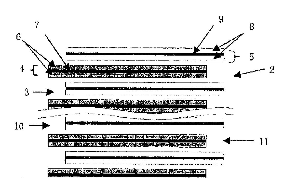
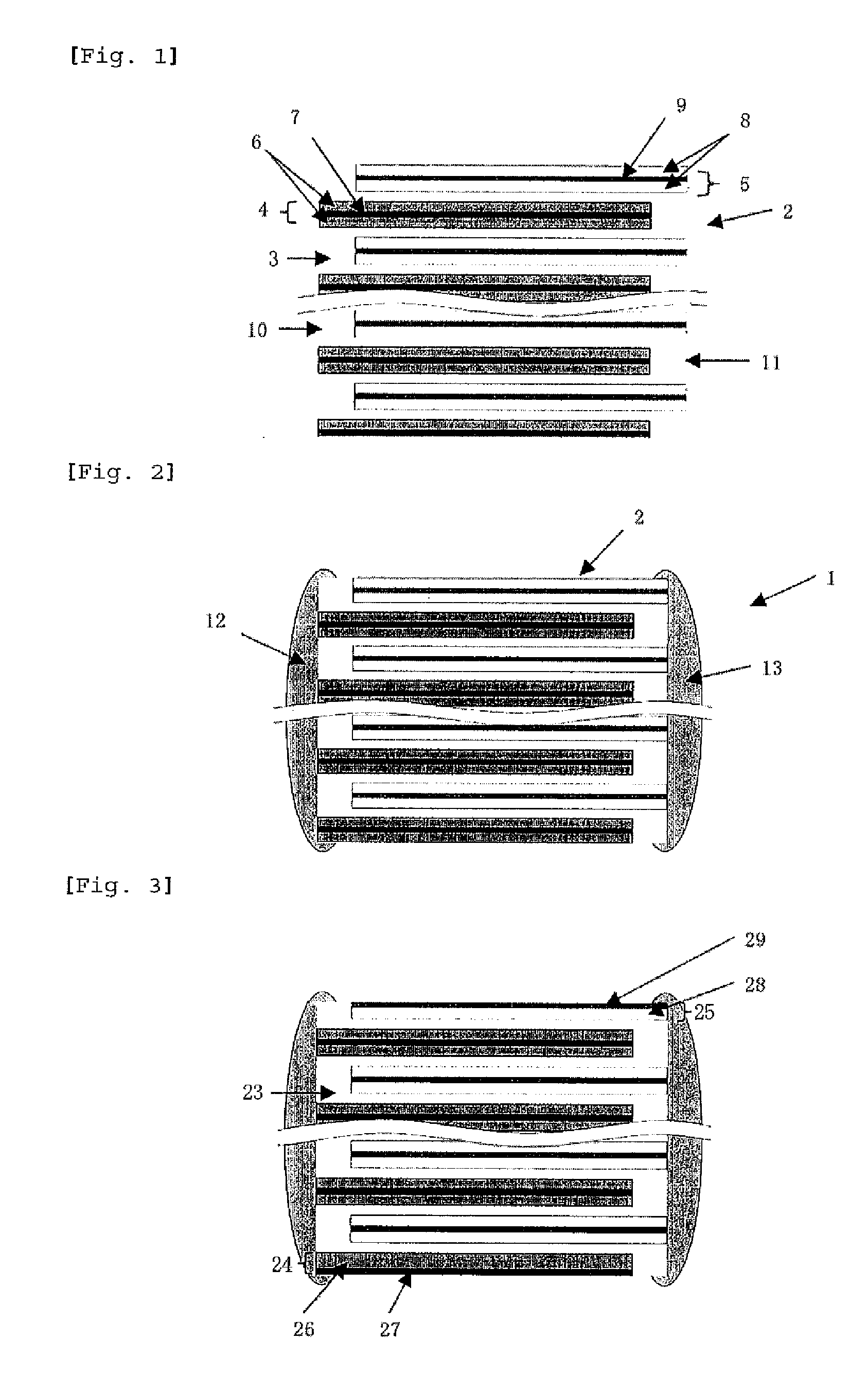
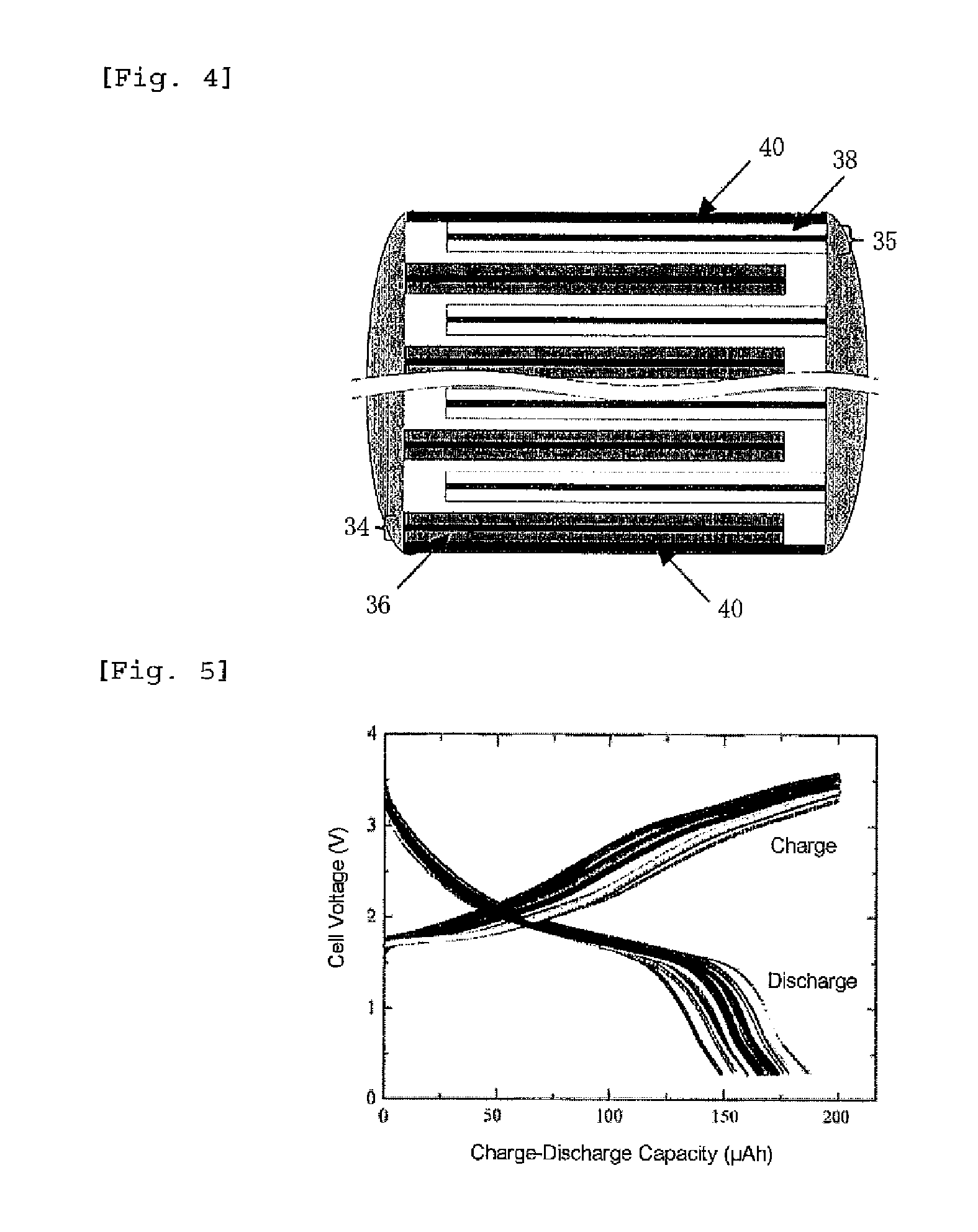
[0020]The all solid state secondary battery of the present invention can be prepared by a method which is simple and easy, and without requiring a long time, and excellent in the point of efficiency, so that it has excellent effects that it can be employed for industrial purpose and a manufacturing cost is in expensive. In addition, in the all solid state secondary battery of the present invention, a laminated material in which a positive-electrode unit and a negative-electrode unit are alternately laminated through an ion-conductive inorganic-material has an effect of excellent in charge-discharge characteristics of a battery. In particular, by co-firing, a laminated material which is a sintered material having good solid-solid surface connection between respective layers can be obtained and a battery having small internal resistance and good energy efficiency can be obtained.

Problems solved by technology

However, in the non-aqueous electrolyte secondary battery, there is pointed out in danger of catching fire since it uses inflammable organic solvent electrolyte, and the organic solvent electrolyte to be used decomposes by a reaction in the electrode to expand an outer can of the battery, and occasionally it causes leakage of the electrolyte.
However, thin-film wholly solid lithium ion secondary batteries disclosed in these prior art references are each produced by a sputtering method, etc., so that a film-formation rate of a thin-film of an electrode or a solid electrolyte is extremely slow.
It is extremely difficult to employ such a method with a slow film-formation rate for Indus-trial purpose in the point of productivity, as well as in the point of manufacturing costs.
However, the technique of Patent Literature 3 is characterized in that a positive active material layer, a solid electrolyte layer and a negative active material layer are laminated so that they are in symmetric interposing both surfaces of a collector on a flat plate, but such a manner of lamination is not extremely practical in industrial points of view and it is clear that it is not suitable for making a multi-layered structure.

Method used


Image

  • All solid state secondary battery
  • All solid state secondary battery
  • All solid state secondary battery

Examples


example 1

Preparation of Positive-Electrode Paste

[0079]As the positive active material, LiMn2O4 prepared by the following method was used.

[0080]Li2CO3 and MnCO3 were used as starting materials, and they were weighed with a molar ratio of 1:4, subjected to wet mixing by a ball mill using water as a dispersing medium for 16 hours, and then, dehydrated and dried. The obtained powder was calcined in air at 800° C. for 2 hours. The calcined product was roughly pulverized, subjected to wet mixing by a ball mill using water as a dispersing medium for 16 hours, and then, dehydrated and dried to obtain calcined powder of a positive active material. An average particle diameter of the calcined powder was 0.30 μm. Also, the composition is to be LiMn2O4 was confirmed by using an X-ray diffraction device.

[0081]As a positive-electrode paste, to 100 parts of the calcined powder of a positive active material were added 15 parts of ethyl cellulose as a binder and 65 parts of dihydroterpineol as a solvent, and...

example 2

[0099]In the same manner as in Example 1 except for changing the calcination temperature to a temperature as shown in Table 1, the positive active material, the negative active material and the calcined powder of an ion-conductive inorganic-material were obtained. With regard to each calcined powder, a linear shrinkage rate was measured as follows. The results are shown in Table 1.

(1) Powder which is an object to be measured was pressed with 0.5 t / cm2 [49 MPa] to prepare a test piece with a thickness of 0.8 to 1.2 mm, and cut to prepare a test piece having a length of 1.5 mm, a width of 1.5 mm and a thick-ness of 0.8 to 1.2 mm.

(2) By using a thermal analyzer (manufactured by MacScience Co., Ltd.), change in thickness after heating to a pre-determined temperature was measured while applying a load of 0.44 g / mm2 to the test piece according to the thermo-mechanical analysis method.

(3) The measured value was substituted to the following equation to obtain a linear shrinkage rate.

Linears...


PUM

PropertyMeasurementUnit
Temperatureaaaaaaaaaa

Abstract

This is to provide an all solid state secondary battery which can be produced by an industrially employable method capable of mass-production and has excellent secondary battery characteristics.This is an all solid state secondary battery containing a laminated material in which a positive-electrode unit and a negative-electrode unit are laminated alternately through an ion conductive inorganic-material layer, the positive-electrode unit has positive active material layers on both surfaces of a positive-electrode collector layer, the above-mentioned negative-electrode unit has negative active material layers on both surfaces of a negative-electrode collector layer, (A) at least one of the positive-electrode collector layer and the negative-electrode collector layer comprises a metal of either of Ag, Pd, Au and Pt, or an alloy containing either of Ag, Pd, Au and Pt, or a mixture containing two or more kinds selected from the metals and alloys, (B) each layer is in a sintered state, or (C) at least the starting material for the ion conductive inorganic material of the ion conductive inorganic-material layer is a calcined powder.

Description

TECHNICAL FIELD[0001]The present invention relates to an all solid state secondary battery which contains a parallel type laminated material which is a product of en block burning (integrally sintered product).BACKGROUND ART[0002]Heretofore, as a secondary battery, optimization of a positive active material, a negative active material and an organic solvent electrolyte, etc., to be used has been carried out mainly in a non-aqueous electrolyte secondary battery (lithium ion secondary battery) using an organic solvent. A produced amount of the non-aqueous electrolyte secondary battery is markedly increasing accompanying with remarkable development of digital home appliances using the battery.[0003]However, in the non-aqueous electrolyte secondary battery, there is pointed out in danger of catching fire since it uses inflammable organic solvent electrolyte, and the organic solvent electrolyte to be used decomposes by a reaction in the electrode to expand an outer can of the battery, an...

Claims


Application Information

Patent Timeline
IPC IPC(8): H01M4/40H01M4/24H01M10/00H01M10/0562H01M10/0585H01M10/36
CPCH01M4/661H01M4/666H01M10/044H01M10/0525H01M10/0562H01M10/0585Y10T29/49108H01M4/0404H01M4/0414H01M4/0471H01M4/485H01M4/622Y02E60/122Y02P70/50Y02E60/10H01M10/36H01M4/02H01M4/04
Inventor BABA, MAMORUIWAYA, SHOICHIMASUMURA, HITOSHISATO, HIROSHISASAGAWA, HIROSHISAKAI, NORIYUKIFUJITA, TAKAYUKI
Owner NAMICS CORPORATION
Learn More