
Organic light emitting device

a light-emitting device and organic technology, applied in the direction of discharge tube luminescnet screens, discharge tube/lamp details, electric discharge lamps, etc., can solve the problems of power consumption reduction, limited efficiency and lifetime improvement of conventional organic light-emitting devices, etc., to improve light-emitting efficiency and lifetime, reduce power consumption, and improve driving voltage

Inactive Publication Date: 2009-07-02
SAMSUNG MOBILE DISPLAY CO LTD
View PDF25 Cites 31 Cited by
  • Summary
  • Abstract
  • Description
  • Claims
  • Application Information

AI Technical Summary

Benefits of technology

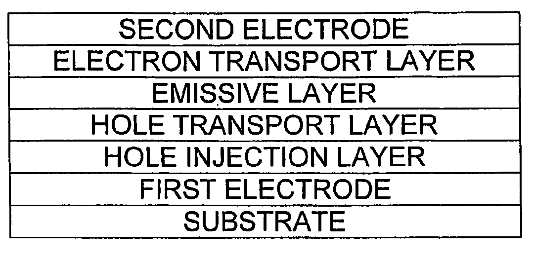
[0007]Aspects of the present invention provide an organic light emitting device that has reduced power consumption due to a voltage reduction by introducing novel hole injection material and novel electron transporting material, and which has improved driving voltage, light emitting efficiency and lifetime.
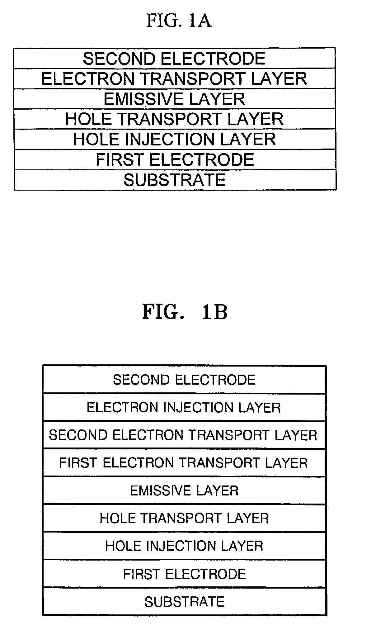
[0011]The organic light emitting device according to aspects of the present invention has excellent electrical properties, and uses a novel hole injecting material that is suitable for use in fluorescent and phosphorescent devices with any kind of colors, such as red, green, blue, white, or the like. In addition, the organic light emitting device according to aspects of the present invention uses a novel electron transporting material, and thus has improved electron injection ability such that a separate electron injection layer is not necessary. Therefore, compared with the case when a conventional electron transporting material is used, the organic light emitting device according to aspects of the present invention using the novel electron transporting material has improved current and power efficiencies, and has improved driving voltage and lifetime by adjusting the balance of charges injected into an emissive layer. Due to such configuration of the organic light emitting device according to aspects of the present invention, charge injection barriers can be reduced, resulting in reduction in power consumption, and the current efficiency can be maximized by adjusting a charge mobility of the novel hole injecting and electron transporting materials.

Problems solved by technology

In addition, conventional organic light emitting devices are limited in terms of the amount of efficiency and lifetime improvements and power consumption reduction that is possible.

Method used


Image

  • Organic light emitting device
  • Organic light emitting device
  • Organic light emitting device

Examples


example 1

Manufacture of Organic Light Emitting Device

[0067]As an anode, a Corning 15 Ω / cm2 (1200 Å) ITO glass substrate was cut to a size of 50 mm×50 mm×0.7 mm, and was ultrasonically washed with isopropyl alcohol and pure water for 5 minutes, respectively. The ITO glass substrate was irradiated with ultraviolet rays for 30 minutes and washed with ozone.

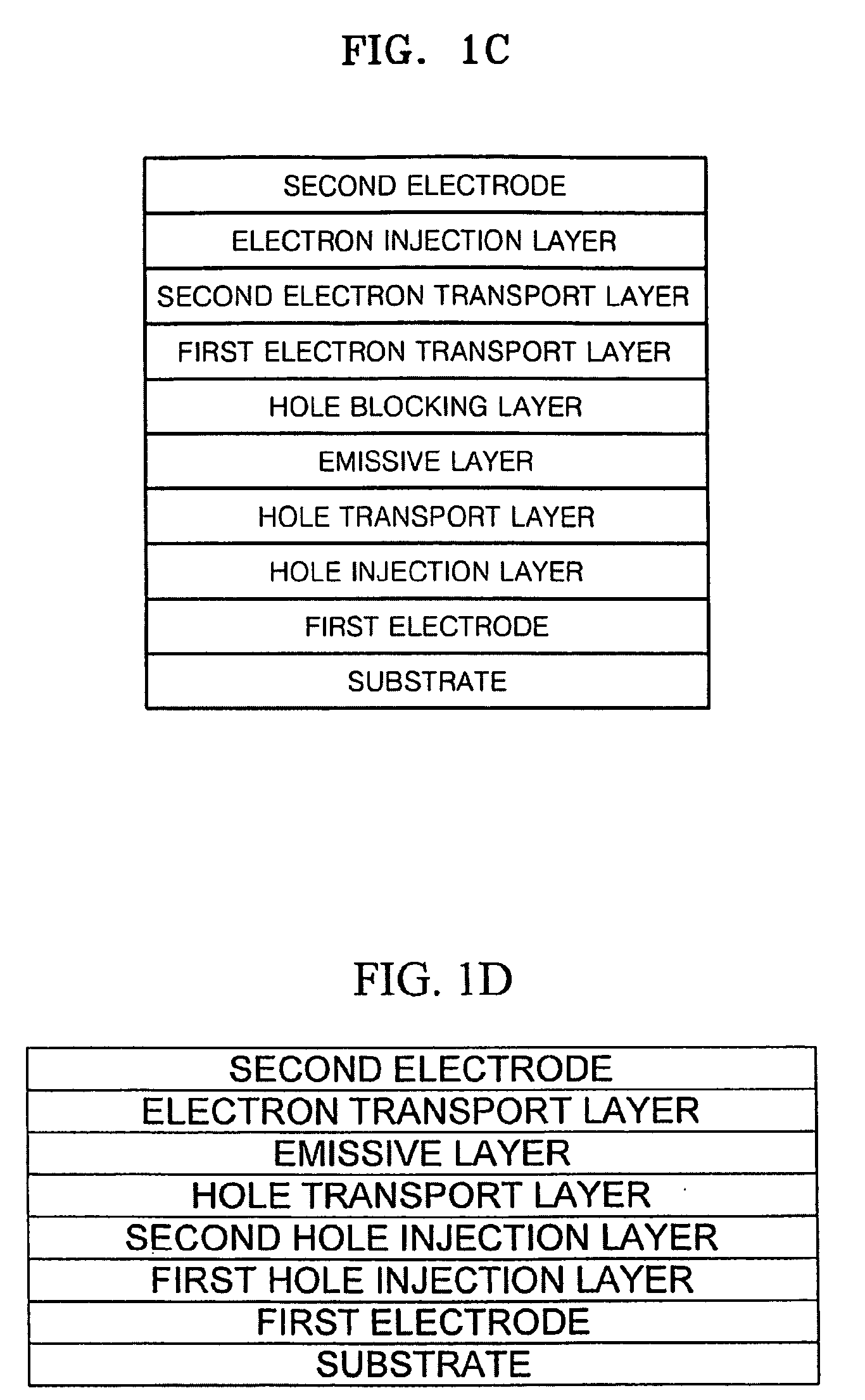
[0068]Then, molybdenum oxide and NPB were co-deposited on the substrate to form a first hole injection layer with a thickness of 100 Å. Subsequently, F16-TCNQ was coated on the first hole injection layer to form a second hole injection layer.

[0069]NPB was vacuum deposited on the second hole injection layer to form a hole transport layer having a thickness of 60 nm. After the formation of the hole transport layer, 100 parts by weight of Alq3 as a host and 5 parts by weight of C545T as a dopant were vacuum deposited on the hole transport layer to form an emissive layer.

[0070]Then, 50 parts by weight of LiF and 50 parts by weight of BeBq2 were v...

example 2

Manufacture of Organic Light Emitting Device

[0072]An organic light emitting device was manufactured in the same manner as in Example 1, except that 50 parts by weight of lithium quinolate and 50 parts by weight of BeBq2 were vacuum co-deposited to form the electron transport layer.

example 3

Manufacture of Organic Light Emitting Device

[0073]As an anode, a Corning 15 Ω / cm2 (1200 Å) ITO glass substrate was cut to a size of 50 mm×50 mm×0.7 mm, and was ultrasonically washed with isopropyl alcohol and pure water for 5 minutes, respectively. The ITO glass substrate was irradiated with ultraviolet rays for 30 minutes and washed with ozone.

[0074]A hole injection layer formed of CuPc was formed on the substrate to a thickness of 10 nm.

[0075]NPB was vacuum deposited on the hole injection layer to form a hole transport layer having a thickness of 60 nm. After the formation of the hole transport layer, 100 parts by weight of Alq3 as a host and 5 parts by weight of C545T as a dopant were vacuum deposited on the hole transport layer to form an emissive layer.

[0076]Then, Bebq2 was vacuum deposited on the emissive layer to form a first electron transport layer (ETL1) having a thickness of 10 nm.

[0077]30 parts by weight of LiF and 70 parts by weight of Bebq2 were vacuum co-deposited on ...


PUM


Abstract

An organic light emitting device includes a first electrode; a second electrode; an emissive layer disposed between the first electrode and the second electrode; a first hole injection layer disposed between the first electrode and the emissive layer; and a first electron transport layer disposed between the emissive layer and the second electrode. The hole injection layer includes a hole injecting material and a first compound made up of an element selected from the group consisting of Mo, Li, Na, K, Rb, Cs, Be, Mg, Ca, Sr, Ba, and B and an element selected from the group consisting of O, F, S, Cl, Se, Br, and I. The electron transport layer comprises an electron transporting material and a second compound, which is Li2O, MoO3, BaO, or B2O3.

Description

CROSS-REFERENCE TO RELATED APPLICATION[0001]This application claims the benefit of Korean Application No. 2007-140555, filed Dec. 28, 2007, in the Korean Intellectual Property Office, the disclosure of which is incorporated herein by reference.BACKGROUND OF THE INVENTION[0002]1. Field of the Invention[0003]Aspects of the present invention relate to an organic light emitting device, and more particularly, to an organic light emitting device with improved driving voltage, light emitting efficiency, lifetime, and the like by using a novel hole injecting material and a novel electron transporting material. In addition, aspects of the present invention may contribute to development of a high image quality organic light emitting device, and provide an organic light emitting device with reduced power consumption and improved lifetime.[0004]2. Description of the Related Art[0005]Organic light emitting devices are devices in which, when a current is supplied to an organic layer interposed be...

Claims


Application Information

Patent Timeline
Patent Type & Authority Applications(United States)
IPC IPC(8): H01J1/63
CPCH01L51/001H01L51/0051H01L51/0058H01L51/5088H01L51/0077H01L51/5048H01L51/0059H10K71/164H10K85/611H10K85/631H10K85/626H10K85/30H10K50/14H10K50/17H05B33/20
Inventor SONG, WON-JUNSUNG, YEUN-JOOKIM, MU-HYUN
Owner SAMSUNG MOBILE DISPLAY CO LTD
Learn More