
Catalyst arrangement construction of motorcycle

Active Publication Date: 2009-07-02
HONDA MOTOR CO LTD
View PDF10 Cites 7 Cited by
  • Summary
  • Abstract
  • Description
  • Claims
  • Application Information

AI Technical Summary

Benefits of technology

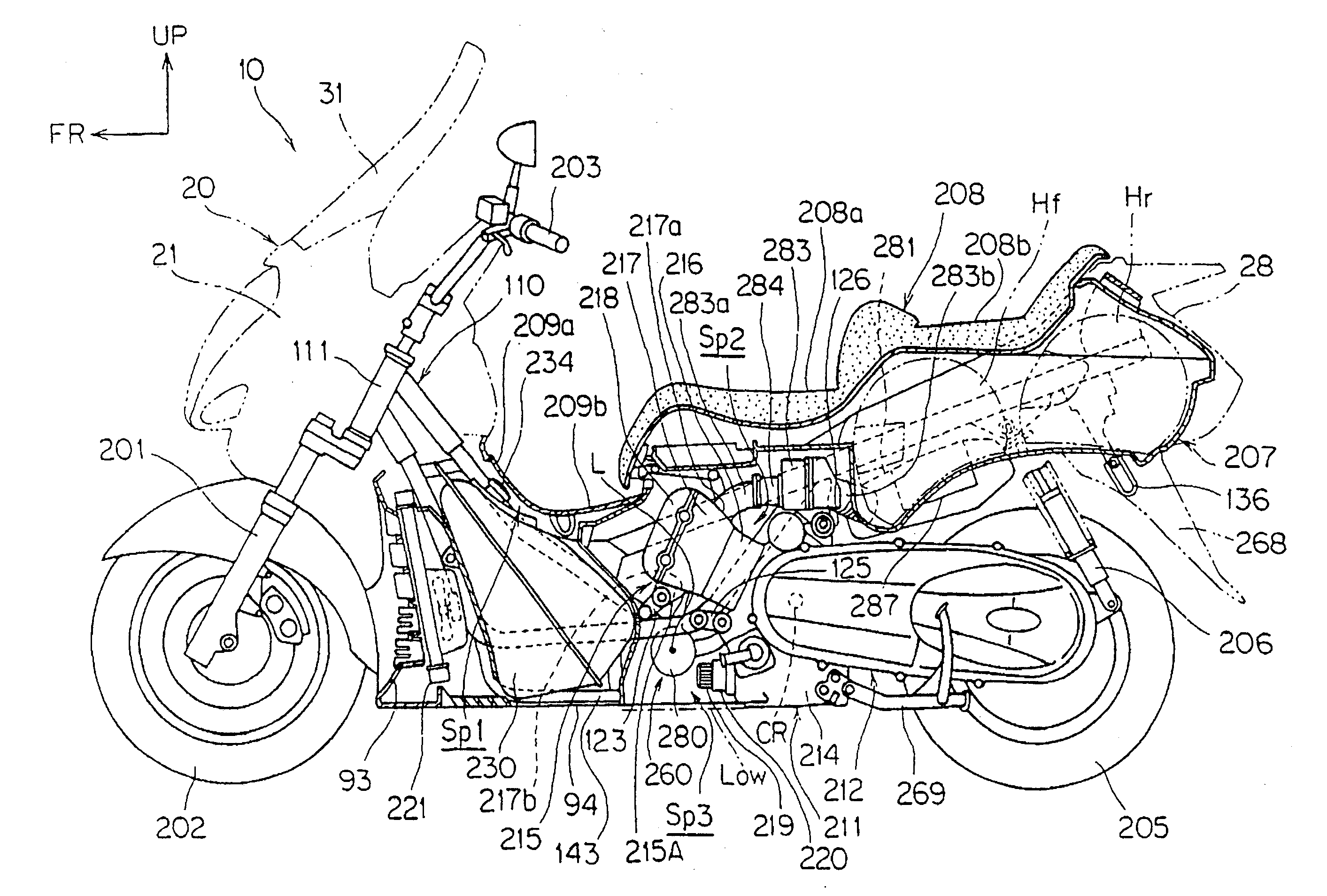
[0008]According to the present invention, because the catalyst storage chamber is arranged in the space which is the lower side of the front surface of the cylinder of the engine and the front side of the front surface of the crankcase and is formed at the upper side of the horizontal plane which substantially horizontally extends from the bottom surface of the crankcase in such a manner that the axis of the catalyst storage chamber is parallel to the axis of the crankshaft, the catalyst converter can be compactly arranged while a lowest ground clearance is ensured, and the empty space which is surrounded by the cylinder and the crankcase of the engine is effectively used.
[0020]Furthermore, because the catalyst storage chamber is arranged at the rear side of the fuel tank which is a component with a large size among the body function components, the exposure of the catalyst storage chamber to the traveling wind can be restricted.

Problems solved by technology

However, in the vehicle where the engine of a moderate engine displacement is mounted, because the catalyst becomes large to be proportional to the engine displacement, the catalyst converter also becomes large.
Therefore, in this kind of vehicle, the catalyst converter with the relatively large capacity cannot be arranged compactly.

Method used


Image

  • Catalyst arrangement construction of motorcycle
  • Catalyst arrangement construction of motorcycle
  • Catalyst arrangement construction of motorcycle

Examples


first embodiment

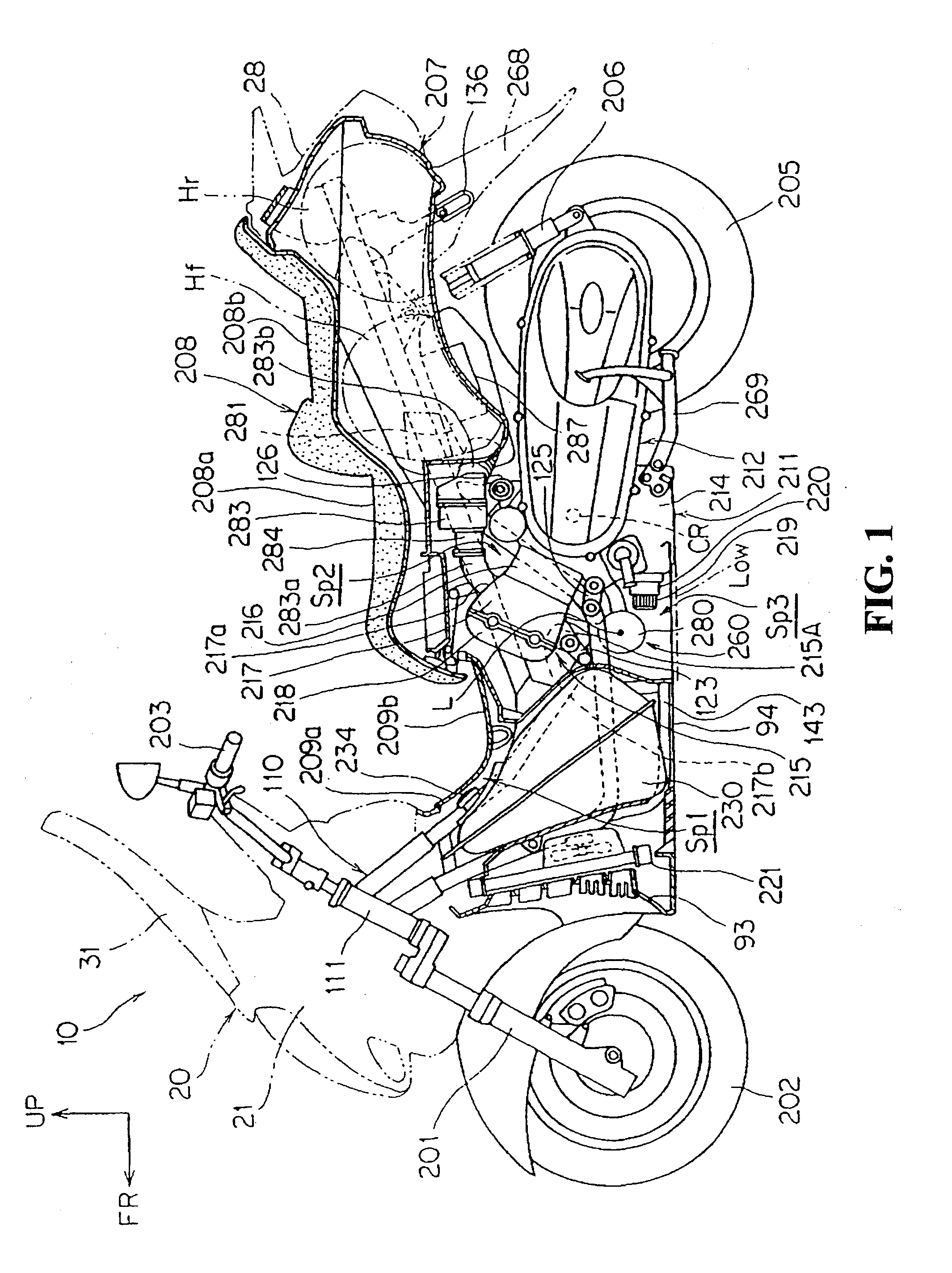
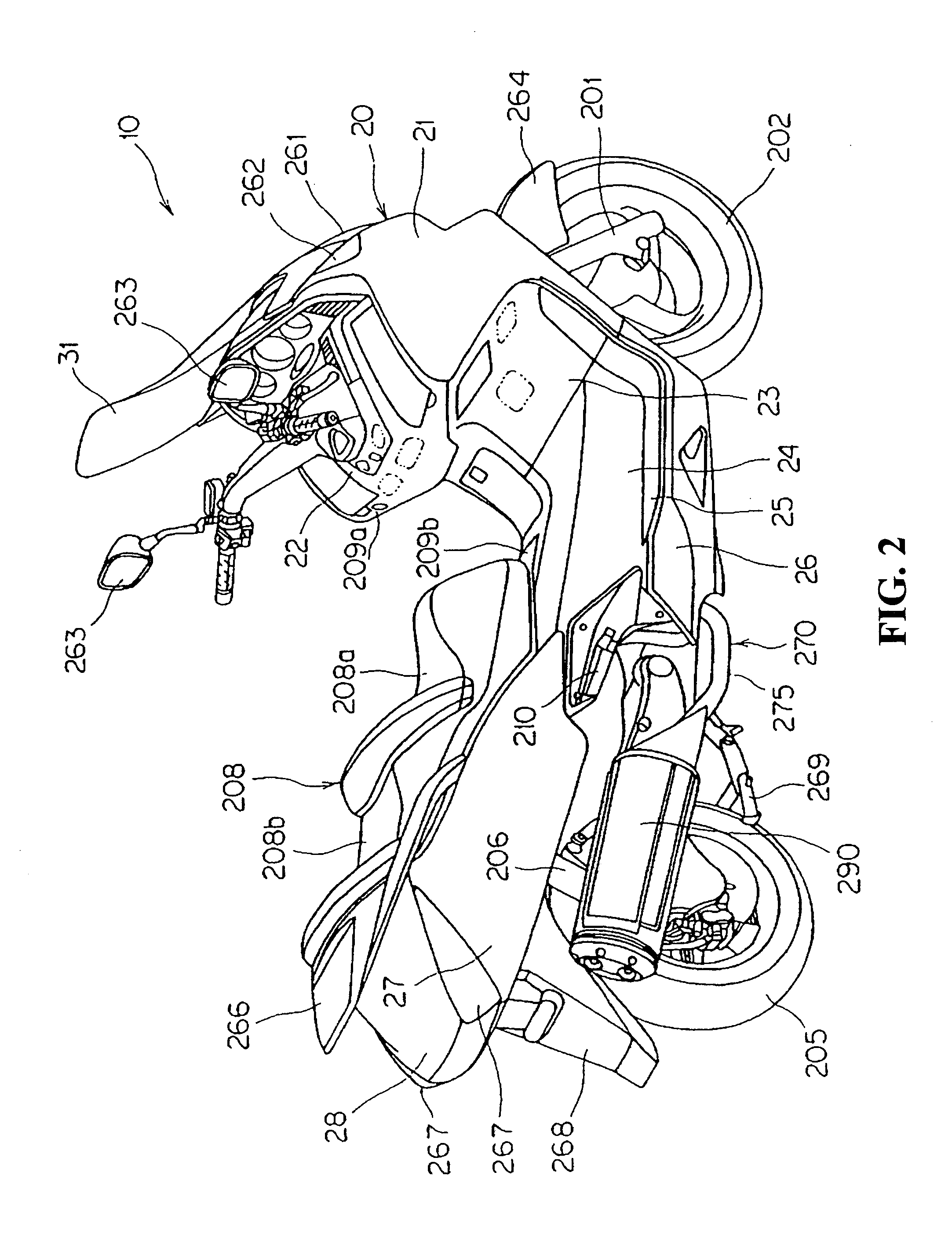
[0035]FIG. 1 is a side view of a motorcycle and FIG. 2 is a perspective view when being viewed from a slant rear portion of the right side of the motorcycle. A motorcycle 10 is a vehicle of a scooter type which has a floor 25 of a low-floor type (with reference to FIG. 2).

[0036]As shown in FIG. 1, the motorcycle 10 has a body frame 110, a pair of right and left forks 201, 201 which are rotatably supported at a head pipe 111 of the body frame 110, a front wheel 202 which is rotatably supported at the front forks 201, 201, a handlebar 203 for steering which is connected to the front forks 201, 201, an engine 211 which is supported at a rear portion of the body frame 110, a power transmission mechanism 212 which is swingable, independent of the engine 211, in the up-down direction with a crankshaft CR of the engine 211 as a center, a rear wheel 205 which is supported at a rear portion of the power transmission mechanism 212, a pair of right and left rear cushion units 206, 206 which a...

second embodiment

[0076]FIG. 8 is a side view of a motorcycle according to a FIG. 9 shows a state where an engine is supported at a body frame. FIG. 10 is a front view which shows the engine along with the periphery construction thereof. In this embodiment, a mode where a catalyst converter 380 which has a noise reduction construction is arranged in a motorcycle 10 where a parallel three-cylinder engine 300 is mounted will be described. Hereinafter, the substantially same construction with the above-described motorcycle 10 is provided with a same reference numerals to be shown, and the specific description thereof is omitted.

[0077]As shown in FIGS. 8 and 9, the motorcycle 10 is a vehicle having the low-floor type floors 25 which are arranged at the left side and right side of the body frame 110 and horizontally extend to the rear side after extending downward to the rear from the front portion of the body. Moreover, the body frame 110 is covered by the body cover 20, and the engine 300 is mounted be...


PUM


Abstract

An engine has a crankcase, and a cylinder which extends from an upper portion of the crankcase toward a front side. In a space which is formed at an upper side of a horizontal plane which substantially horizontally extends from a bottom surface of the crankcase, a catalyst storage chamber is arranged in such a manner that an axis of the catalyst converter is in a direction of a crankshaft. The space is arranged just below a front surface of the cylinder and forward of a front surface of the crankcase.

Description

TECHNICAL FIELD[0001]The present invention relates to a catalyst arrangement construction of a motorcycle having a catalyst storage chamber in an exhaust pipe between an exhaust port and an exhaust muffler of an engine.BACKGROUND OF THE INVENTION[0002]In a motorcycle where a single-cylinder engine of a small engine displacement is mounted, an exhaust pipe extends from the engine to a lower side of a crankcase and a catalyst converter is connected with the exhaust pipe at the lower side of the crankcase. Moreover, an outlet of the catalyst converter is connected to an exhaust muffler of a rear portion of the vehicle through another exhaust pipe. The motorcycle having the above-described construction has been disclosed (with reference to JP-A No. 2006-226279, for example).[0003]In this motorcycle, exhaust gas which has a high temperature and is exhausted from the engine is supplied to a catalyst in the catalyst converter before the exhaust gas reaches the exhaust muffler. Therefore, t...

Claims


Application Information

Patent Timeline
IPC IPC(8): F01N3/10B62J31/00B62J35/00B62M7/02F01N3/28F01N13/08
CPCF01N3/2885F01N2590/04F01N2490/06F01N13/08Y02A50/20
Inventor MITSUKAWA, MAKOTOHONDA, KOICHIRO
Owner HONDA MOTOR CO LTD
Learn More