
Image forming method

Inactive Publication Date: 2009-05-14
KONICA MINOLTA BUSINESS TECH INC
View PDF4 Cites 6 Cited by
  • Summary
  • Abstract
  • Description
  • Claims
  • Application Information

AI Technical Summary

Benefits of technology

[0007]It is an object of the invention to provide an image forming method which can inhibit a phenomenon of deposition of microparticles on the surface of an electrophotographic photoreceptor even when a low Tg toner in the presence of a lubricant and an electrophotographic photoreceptor used therein.

Problems solved by technology

As is known, however, problems arise with the use of a toner of a low Tg such that toner filming is easily caused on an electrophotographic photoreceptor (hereinafter, also denoted simply as a photoreceptor).
Such a technique may prevent filming of a toner itself but there are problems such that it is difficult to prevent paper powder which is difficult to remove by a cleaning blade or microparticles of external additives added to the toner from adhering onto the photoreceptor.
Electrophotographic photoreceptors are repeatedly used in the electrophotographic process in a cycle of charging, exposure, development, transfer, cleaning and charge-neutralization and are subject to various stresses in the meantime, leading to deterioration of the receptors.
Examples of such deterioration include chemical or electrical deterioration such that strongly oxidative ozone or NOx generated from a corona charger used as a conventional charger chemically damages the light-sensitive layer, carriers (electric current) formed upon imagewise exposure flow into the light-sensitive layer or a photosensitive composition is decomposed by external light Further, examples of mechanical deterioration include wearing of a cleaning brush or a magnetic brush, and abrasion or flaws of the light-sensitive layer surface and its peeling-off, which are due to contact with the developer or paper.
Specifically, such damage formed on the photoreceptor surface easily occur on copied images and directly vitiate image quality, leading to factors limiting the lifetime of a photoreceptor.
However, since the doping amount of the charge transport material is large, sufficient mechanical strength has not yet been achieved.

Method used


Image

  • Image forming method
  • Image forming method
  • Image forming method

Examples


examples

[0196]The present invention will be further described with reference to examples and comparisons but the invention is by no means limited to these. Unless otherwise noted, “part(s)” in examples presents part(s) by mass.

Preparation of Photoreceptor 1:

[0197]Electrophotographic photoreceptor 1 was prepared in such a manner as below.

[0198]The surface of a cylindrical aluminum support was subjected to machine-cutting to prepare an electrically conductive support exhibiting a ten point surface roughness (Rz) of 1.5 μm.

Intermediate Layer:

[0199]The following intermediate layer dispersion was diluted to two times with the same solvent and after allowed to stand over one day and night, was filtered with a filter (lysimesh 5 μm filter, produced by Nippon Pole Co.) to prepare a coating solution of an intermediate layer.

Polyamide resin CM 800 (produced1partby Toray Co.)Inorganic particles: titanium oxide*3partsMethanol10parts*titanium oxide having a number average primary particle size of 35 nm...


PUM

PropertyMeasurementUnit
Temperatureaaaaaaaaaa
Speedaaaaaaaaaa
Glass transition temperatureaaaaaaaaaa

Abstract

An electrophotographic image forming method is disclosed, wherein a cylindrical developing sleeve carrying a developer is brought into contact with a photoreceptor with rotating the developing sleeve in the counter direction to the rotation of the photoreceptor, and a lubricant is supplied to the photoreceptor and the photoreceptor comprises a uppermost surface layer containing a polyarylate having a structure unit represented by the following formula and the toner comprises toner particles exhibiting a glass transition temperature of from 16 to 44° C.

Description

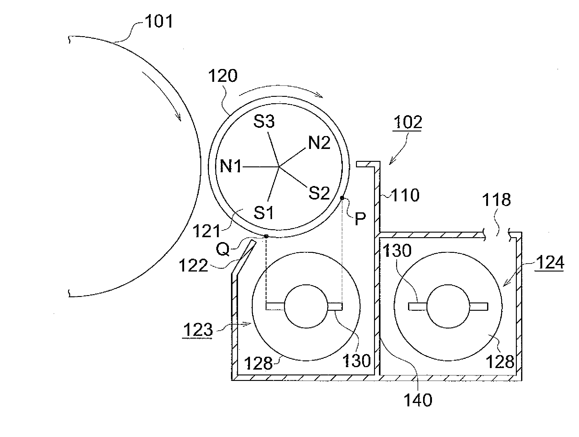
FIELD OF THE INVENTION[0001]The present invention relates to an image forming method.BACKGROUND OF THE INVENTION[0002]In the market of color POD, there has increased desire for low temperature fixing of toners toward energy saving as well as enhancement of image quality and speed Setting a glass transition temperature (hereinafter, also denoted simply as Tg) of a toner resin as low as possible is effective for lowering the fixing temperature. As is known, however, problems arise with the use of a toner of a low Tg such that toner filming is easily caused on an electrophotographic photoreceptor (hereinafter, also denoted simply as a photoreceptor). It is known as a means for preventing toner filming to supply a lubricant onto the photoreceptor surface to achieve enhanced releasability from the surface. Such a technique may prevent filming of a toner itself but there are problems such that it is difficult to prevent paper powder which is difficult to remove by a cleaning blade or micr...

Claims


Application Information

Patent Timeline
IPC IPC(8): G03G13/04
CPCG03G5/14756G03G13/08G03G9/08797G03G9/0804
Inventor ITAMI, AKIHIKOSAKAI, EIICHIETO, YOSHIHIKOOSHIBA, TAKEO
Owner KONICA MINOLTA BUSINESS TECH INC
Learn More