
Methods for manufacturing printed circuit boards using a partial printing process and apparatus

Inactive Publication Date: 2005-01-11
INTEL CORP
View PDF11 Cites 3 Cited by
  • Summary
  • Abstract
  • Description
  • Claims
  • Application Information

AI Technical Summary

Benefits of technology

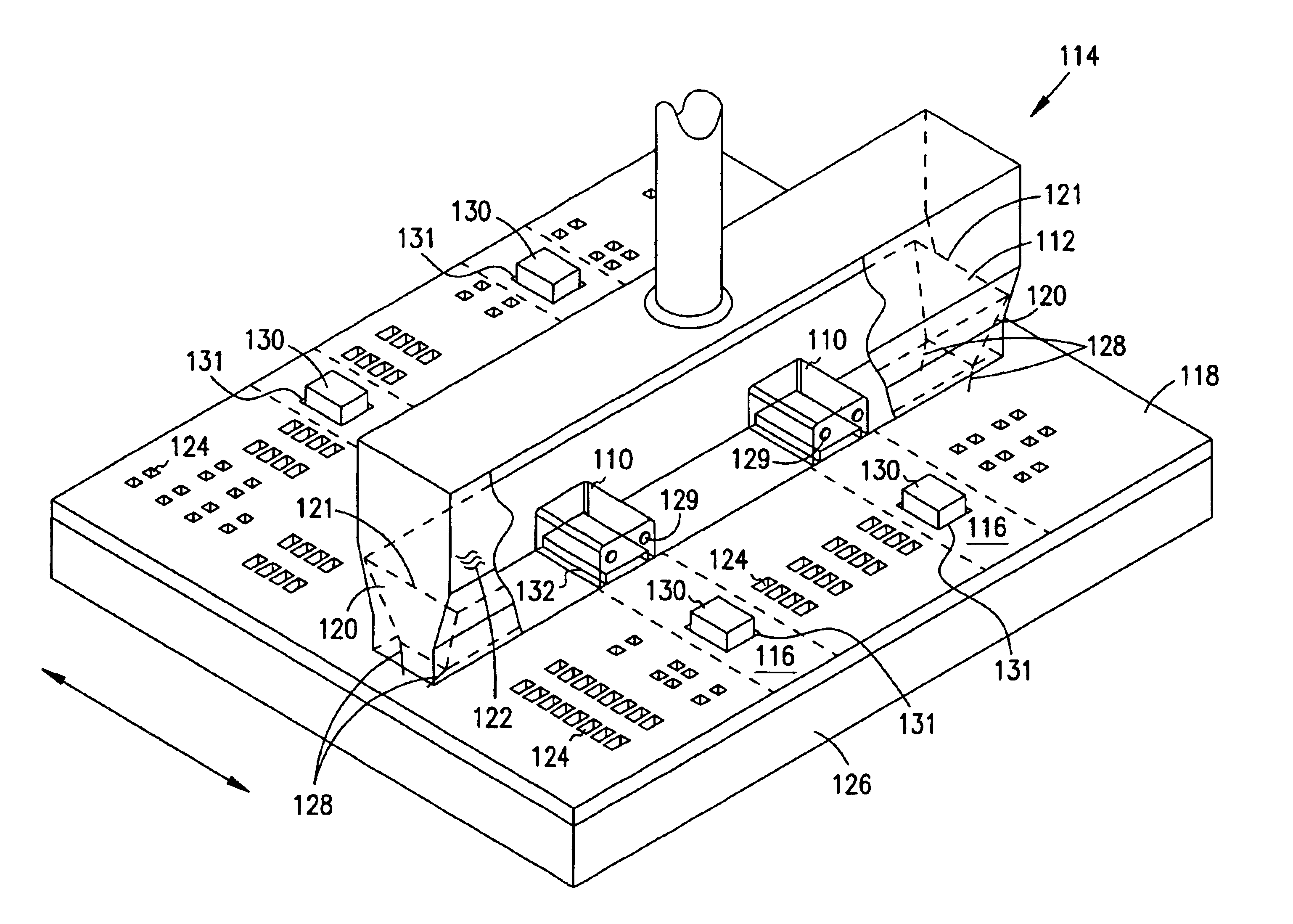
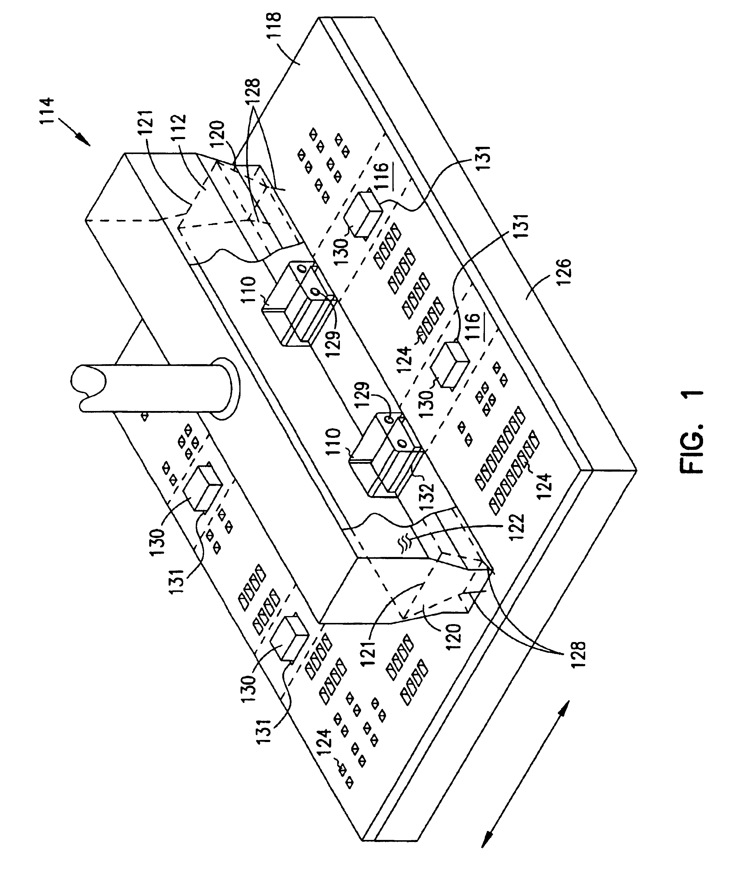
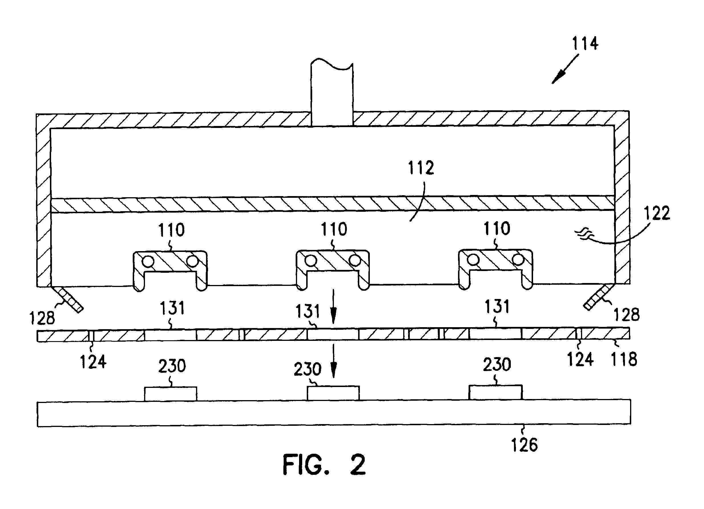
An apparatus for preventing media deposition in predetermined locations comprising at least one blocking cap connected to a pressurized squeegee head is disclosed. In one embodiment, a method for partially printing a circuit board is disclosed. The method comprises inserting one or more blocking caps inside a pressurized squeegee head and printing with the pressurized squeegee head. In this way, defined areas on the surface of a stencil or screen, over which the blocking caps travel, are skip

Problems solved by technology

Full printing, however, provides limited flexibility in terms of being able to apply components at different times, as the surface over which the squeegee blade or head travels needs to be substantially planar.
Failure of a die after it and all of the other components have been added to the circuit board can be costly.
Such packages are costly to produce, however, and failure of the die after it is part of the package is also expensive.
Such cost concerns have caused many manufacturers to limit their designs so as to produce smaller packages, eliminate large or heavy parts, avoid double-sided circuit boards, and so forth.
However, the same problem of costly die failure exists.
This method is very slow, however, because the paste is dispensed onto only one pad or “land” at a time.
Clogging of needles is also a common problem with this method.
Special dispense heads can be used to reduce the cycle time, although this increases the costs of the process significantly.
Furthermore, due to the high cost of these processes, the complexity of the circuit board or module design is limited.

Method used


Image

  • Methods for manufacturing printed circuit boards using a partial printing process and apparatus
  • Methods for manufacturing printed circuit boards using a partial printing process and apparatus
  • Methods for manufacturing printed circuit boards using a partial printing process and apparatus

Examples


Embodiment Construction

An apparatus and method for partially printing circuit boards is disclosed. In the following detailed description, reference is made to the accompanying drawings which form a part hereof, and in which is shown by way of illustration specific embodiments in which the inventions may be practiced. In the drawings, like numerals describe substantially similar components throughout the several views. These embodiments are described in sufficient detail to enable those skilled in the art to practice the invention, and it is to be understood that other embodiments may be utilized and that mechanical, procedural, electrical and other changes may be made without departing from the spirit and scope of the present inventions. The following detailed description is, therefore, not to be taken in a limiting sense, and the scope of the present invention is defined only by the appended claims, along with the full scope of equivalents to which such claims are entitled.

In one embodiment, a blocking c...


PUM


Abstract

An apparatus for preventing media deposition in predetermined locations comprising at least one blocking cap connected to a pressurized squeegee head is disclosed. In one embodiment, a method for partially printing a circuit board is disclosed. The method comprises inserting one or more blocking caps inside a pressurized squeegee head and printing with the pressurized squeegee head. In this way, defined areas on the surface of a stencil or screen, over which the blocking caps travel, are skipped. In another embodiment, a new method for manufacturing printed circuit boards is described, comprising placing a component on a circuit board, performing burn-in or testing of the component, partially printing attachment media on the circuit board with a pressurized squeegee head containing one or more blocking caps, and placing additional components on the circuit board. In one embodiment, the circuit board is sold or returned to the circuit board designer before performing the partial printing step.

Description

FIELDThis invention relates generally to circuit board printing processes, and in particular, the present invention relates to methods for manufacturing printed circuit boards using a partial printing process and apparatus.BACKGROUNDSurface mounting involves a planar mounting of components to a circuit board having a previously-applied conductive pattern. The components may be individual surface-mounted components, flip chips, tape automated bonding formats, and so forth. The conductive pattern for most components is obtained by a printing process that involves depositing a layer of attachment media, such as solder paste, onto a stencil or screen. Solder is forced through openings in the stencil or screen onto pads located on the circuit board below using a conventional squeegee blade. Alternatively, pressurized squeegee heads having two squeegee blades can be used to apply the solder with the use of internal pressure, by either rolling it onto the stencil or forcing it through the ...

Claims


Application Information

Patent Timeline
IPC IPC(8): H05K3/12
CPCH05K3/1216
Inventor AMIR, DUDI
Owner INTEL CORP
Learn More