Joint and joining method for multilayer composite tubing and fittings

a multi-layer composite tubing and composite tubing technology, applied in the direction of non-disconnectible pipe joints, bends, manufacturing tools, etc., can solve the problems of virtually undetectable joints in piping materials, adverse effects on finished products or affect tests, and water will tend to become contaminated

Inactive Publication Date: 2009-04-23
ORION ENTERPRISES
View PDF29 Cites 8 Cited by
  • Summary
  • Abstract
  • Description
  • Claims
  • Application Information

AI Technical Summary

Benefits of technology

[0009]The present disclosure provides exemplary embodiments of joints and joining methods for connecting multilayer composite tubing and fittings having at least one middle layer of malleable metal. The joint and joining method of the present disclosure prevent the middle layer of malleable metal from being exposed to liquid flow within the joined tubes and fittings and result in an inner surface that has almost no bead protrusion into the fluid flow path so that the joint is acceptable for use in a high purity water system.
[0011]According to one aspect, the ends are flared outwardly such that a small radius at the wetted base of the flare is achieved so that fusion weld beads occupy the space created by the radius, and thereby result in an inner surface that has almost no bead protrusion into the waterway. The flared ends, therefore, make the resulting joint even more acceptable than standard infrared butt fusion welds, which are already widely accepted by the industry.
[0012]The middle layer of malleable metal incorporated into a flared end formed in accordance with the present disclosure would act to reinforce the joint, as well as provide a heat sink to allow the wetted surfaces to be thoroughly and uniformly fused together. The middle layer of malleable metal will also act to prevent problems associated with creep of the thermoplastics, thereby minimizing future potential failures due to creep at the joints.
[0013]Unlike contact butt fusion, and in traditional infrared butt fusion, fusion in accordance with the present disclosure does not occur at the ends of the pipe surface, but rather is being made at flat flange faces that are at a right angle to the flow. Since these small flat faces are produced by flaring material that originates from the inside diameter of the pipe, the material is clean, and will be highly regular in surface shape, and will not need to be subjected to shaving or planning using a rotating cutting or planning tool (a standard step in contact or normal infrared butt fusion). This means that another major potential source of impurity is eliminated whereby metal fragments can be introduced or imbedded into the pipe due to contact with the cutting tools. This feature also serves to make the joints produced from the modified infrared method in this disclosure even cleaner and even more desirable than those produced by traditional infrared butt fusion.
[0014]It is apparent that the joining methods and the resulting joints provided in accordance with the present disclosure have many advantages over previous high purity systems. For example, the presently disclosed joint and joining method makes multilayer composite tubing more practical so that the use of coiled tubes in long lengths that can be rolled out in rigid fashion, together with the field formability of many of the elbows, will eliminate 70 to 90 percent of the joints found in previous high purity systems. Where fusion joints are required, the presently disclosed joint and joining method provides joints having smaller beads joint and less potential for contamination.

Problems solved by technology

Once water has been purified, it must be run through pipes that are very stable, clean and smooth, or the water will tend to become contaminated through impurities it gains from the piping materials.
This is very undesirable in high purity water applications, and particularly in applications where microorganisms can lead to adverse effects on the finished products or affect test results.
The best joint forming techniques that have been developed to date for thermoplastic materials include a technique known as bead and crevice free butt-welding, which results in a virtually undetectable joint in the piping material.
The only drawbacks to this method is that it is very labor intensive, is typically performed on pipes with fixed lengths (e.g. 5 meter extruded lengths and separate fittings) which require a large number of welds, and it is not possible to perform this type of welding on 100% of the joints in the system.
By comparison with traditional contact butt fusion, this reduced and uniform bead result substantially reduces the possibility that bacteria can collect and thrive at the fusion weld seam.

Method used


Image

  • Joint and joining method for multilayer composite tubing and fittings
  • Joint and joining method for multilayer composite tubing and fittings
  • Joint and joining method for multilayer composite tubing and fittings

Examples


Embodiment Construction

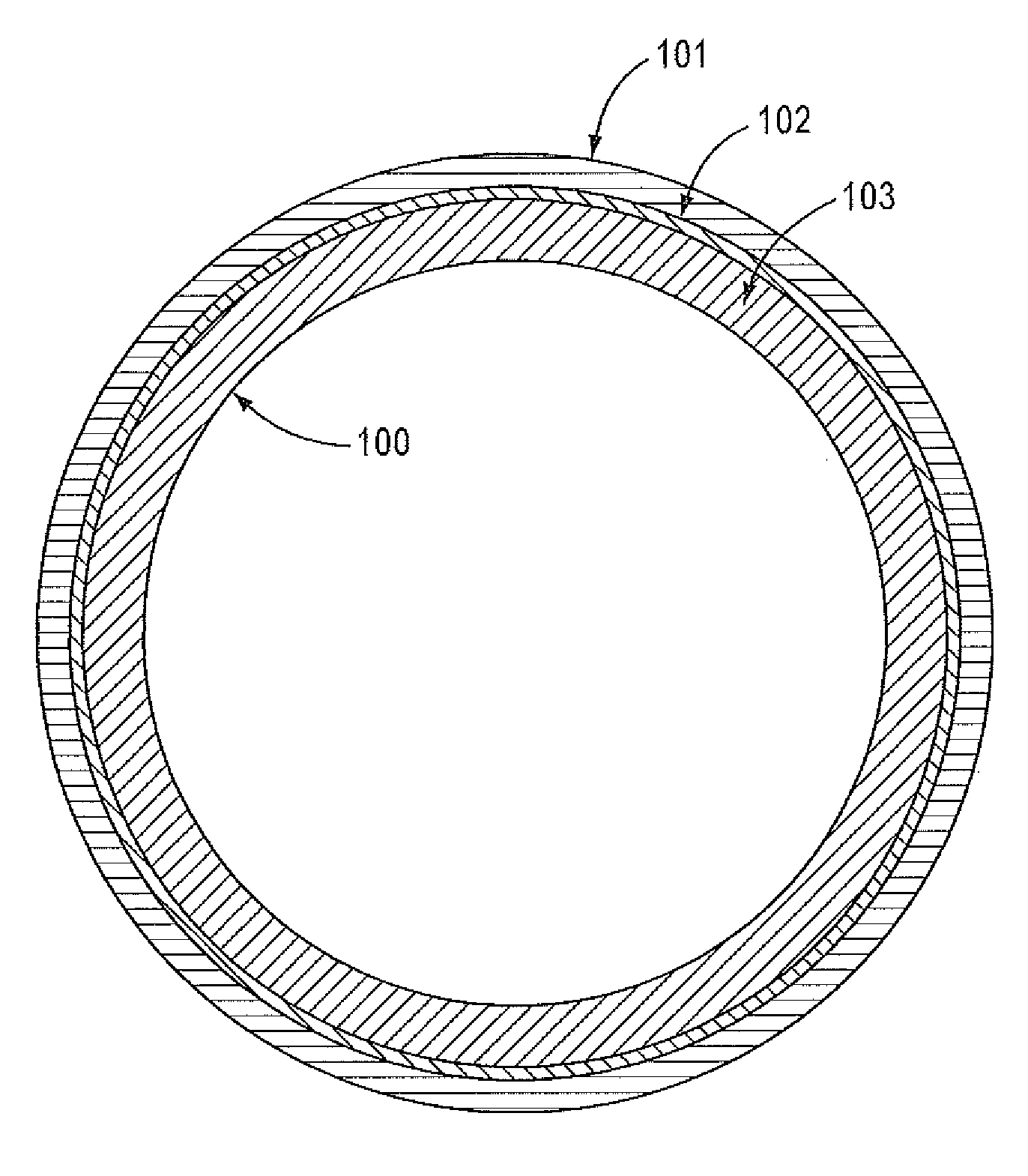
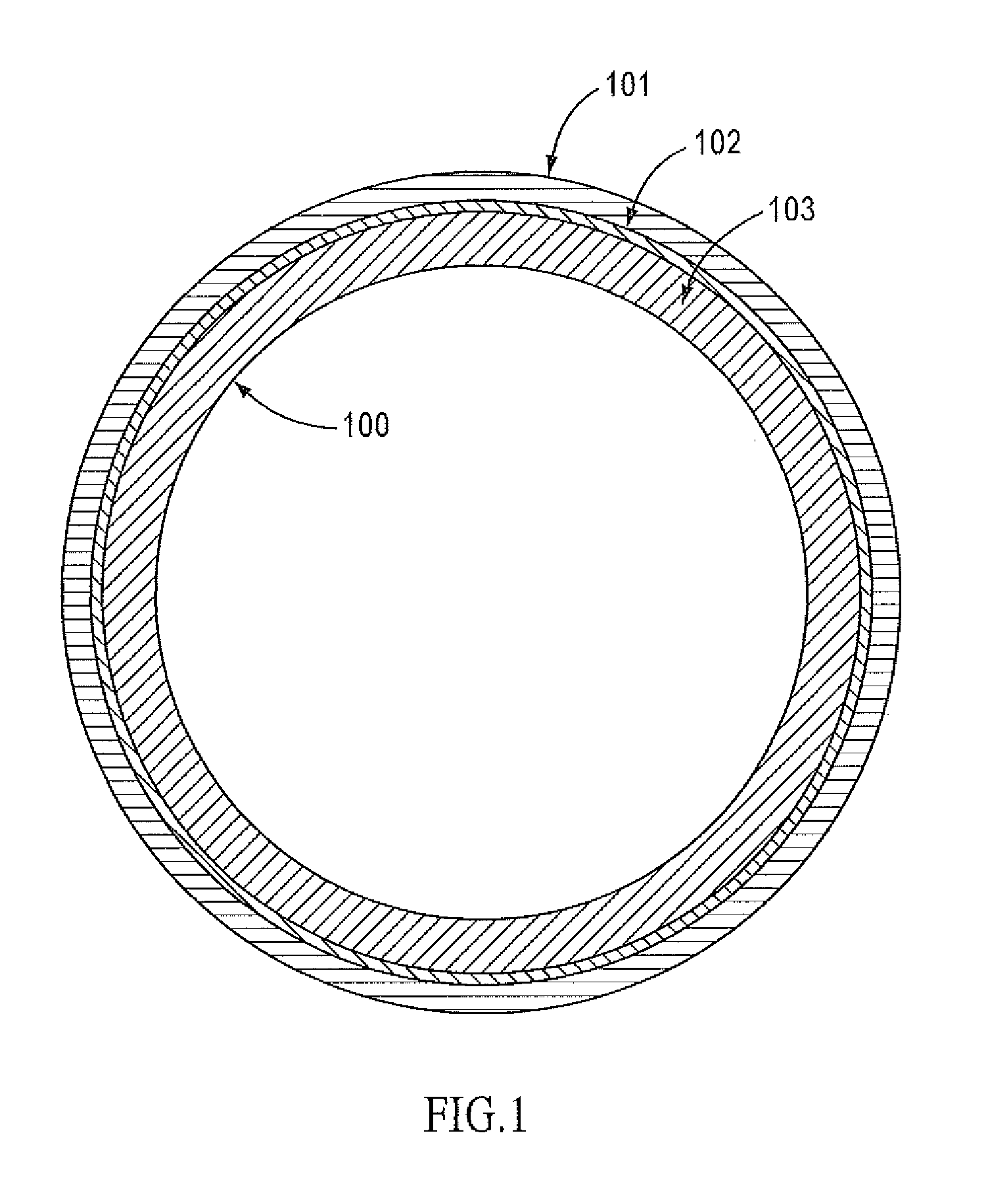
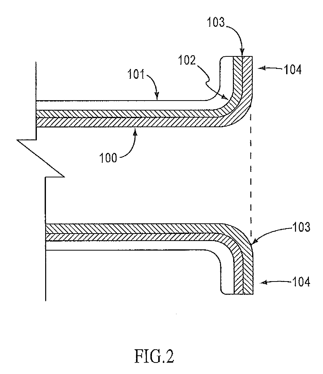
[0026]The present disclosure overcomes many of the prior art problems with joints and joining of high purity water tubing and piping systems. In general, the joints and joining methods are used to create extensive yet highly sanitary plumbing networks. Among other features and benefits, the disclosed joints and joining methods facilitate high quality and strong joints and can create complex networks of piping. The advantages and other features disclosed herein, will become more readily apparent to those having ordinary skills in the art from the following detailed description of exemplary embodiments taken in conjunction with the drawings which set forth representative embodiments of the present disclosure and wherein like reference numerals identify similar structural elements.

[0027]All relative descriptions herein such as upward, downward, left, right, up, down, length height, width, thickness, and the like with reference to the Figures are not meant in a limiting sense. Additiona...


PUM

PropertyMeasurementUnit
Lengthaaaaaaaaaa
Thermoplasticityaaaaaaaaaa

Abstract

A joining method wherein ends of multilayer composite tubing and / or fittings having at least one middle layer of malleable metal are flared radially outwardly so that exposed ends of the middle layer of malleable metal are directed radially outward and away from a fluid flow path within the tubing and / or fittings. The flared-out ends are then fused using infrared butt welding so that the resulting bead protrusion into the fluid flow path is small enough to be acceptable for use in a high purity water system.

Description

CROSS-REFERENCE TO RELATED APPLICATION[0001]This application claims priority to U.S. Provisional Patent Application No. 60 / 980,583, filed Oct. 17, 2007, which is incorporated herein by reference. This application is related to International Application No. PCT / US2007 / 007686 (Atty. Docket No. 65978PCT), which claims priority to U.S. Provisional Patent Application No. 60 / 744,212, filed Apr. 4, 2006, both of which are incorporated herein by reference.TECHNICAL FIELD OF THE DISCLOSURE[0002]The present disclosure relates to a joint and joining method for multilayer composite tubing and fittings having at least one middle layer of malleable metal. The joint and joining method prevent the middle layer from being exposed to liquid flow within the joined tubes and fittings and result in an inner surface that has almost no bead protrusion into the waterway so that the joint is acceptable for use in a high purity water system.BACKGROUND OF THE DISCLOSURE[0003]High purity water (water highly pu...

Claims


Application Information

Patent Timeline
IPC IPC(8): B23P11/00F16L11/04F16L41/00F16L43/00F16L23/00
CPCB29C57/04Y10T29/49826B29C65/1432B29C65/7841B29C66/1312B29C66/5221B29C66/52241B29C66/723B29C66/919B29C2035/0822B29K2023/06B29K2023/065B29K2023/0691B29K2023/12B29K2027/16B29K2101/12B29K2305/00B29K2305/02B29K2305/10B29L2009/003F16L13/0254F16L47/02B29C66/5229B29C66/322B29C66/91231B29C66/91421B29C66/9161B29C65/1412B29C66/7392B29C66/71B29C66/73921B29C66/73941B29C66/73756B29C66/73776B29C66/72325B29C66/72321B29K2023/04B29K2023/10B29K2027/12B29K2023/0683B29K2023/0625
Inventor ZIU, CHRISTOPHER G.
Owner ORION ENTERPRISES
Why Eureka
Try Eureka