Cyclonic system for enhanced separation of fluid samples and the like, and method therefore

a cyclonic system and fluid sample technology, applied in the field of pressurized process fluid sampling, can solve the problems of further complicated, impractical for some applications, and problems such as operation and safety problems, and achieve the effects of preventing destructive liquid flow, reducing sample distortion and flawed analysis, and increasing operation tim

Active Publication Date: 2018-03-06
MAYEAUX HLDG
View PDF49 Cites 11 Cited by
  • Summary
  • Abstract
  • Description
  • Claims
  • Application Information

AI Technical Summary

Benefits of technology

[0027]The preferred embodiment of the present invention thereby provides a redundant system for preventing entrained liquid from entering the sample stream to the analyzer while ensuring that a single gas-phase sample is taken.
[0028]Alternatively, an alternative embodiment provides the cyclonic separator with the liquid block device and no membrane / filter therebetween, substantially increasing operation time between maintenance requirements and no need for membrane / filter changes, albeit without the triple redundancy of the preferred embodiment, so this system is envisioned as being more suitable for less “wet” fluid streams.
[0029]In either embodiment, the present invention reduces or may even eliminate the need for filter elements that must be replaced or cleaned. It protects the entire sample system from contamination that otherwise would require costly downtime for cleaning or replacement. By preventing undesired liquids from entering the sample, the present lessens the likelihood of sample distortion and flawed analysis, especially when utilizing the current API and GPA sampling standards.
[0030]The first, preferred embodiment of the present provides a unique cyclone separator formed to receive fluid flow from an inlet, providing a first stage of liquid separation. The present embodiment then utilizes a coalescing element downstream the cyclone separator / filter, so that the coalescing element coalesces entrained mist or very fine aerosol droplets which might otherwise pass through the cyclone, and thus prevents same from being introduced into the sample system.
[0031]Finally, a liquid block device may be provided downstream to prevent passage of liquid therethrough in the event the coalescing element becomes oversaturated with liquid, resulting in excessive pressure differential, or pass-through of low surface tension liquids which might be unaffected by the coalescing element. Thus the preferred, first embodiment provides two stages of liquid separation with the third stage stopping liquid flow as a fail-safe, thereby preventing destructive liquid flow to any analyzer of the like downstream the system, all in an easily maintained unit having a compact footprint.
[0032]A second embodiment utilizes the first stage cyclone filter, but without any filter or coalescing element of any type behind the cyclone filter to minimize maintenance requirements, although a liquid block may be provided downstream as required.

Problems solved by technology

Hydrocarbon liquid in the gas being transported causes operational and safety problems.
However, these systems can be overwhelmed with excessive liquid loading, causing the maximum allowable differential pressure to be exceeded, which may force liquids through the coalescing elements, and into the sample system.
This can be further complicated by the use of various liquid chemicals, which are routinely injected into the process, gas such as corrosion inhibitors, amine and carbon dioxide inhibitors, as well as chemicals meant to dry the gas, like alcohols and glycols.
Also, some coalescing elements may have temperature limitations, and thus may be impractical for some applications.
These devices are not used to remove entrained liquids from gas samples.
Cyclone separators operate on this principal as well as well as knock-out drums.Liquid / Gas coalescer cartridges, filters, membranes and the like are generally not suitable for removal of liquids in bulk, relying upon inertial impaction, the particles engaging a fibrous mass in a container which may include an indirect pathway utilizing inertial impaction and gravity to collect and drain fluid.Mist Eliminators likewise rely upon the principal of inertial impaction, but instead of plates or baffles, relying upon fibers, meshes or the like.
Removal of such entrained liquid is imperative as a component of gas analysis as detailed above, although such systems are imperfect and many designs can be overwhelmed by a liquid slug or the like.
However, due to shortcomings in the above systems there remains a long felt, but unresolved need for a system with the ability to reliably prevent liquids from overwhelming the separator, thus preventing sample distortion and contamination, which can equate to wrong analysis and very costly incorrect monetary exchanges.

Method used


Image

  • Cyclonic system for enhanced separation of fluid samples and the like, and method therefore
  • Cyclonic system for enhanced separation of fluid samples and the like, and method therefore
  • Cyclonic system for enhanced separation of fluid samples and the like, and method therefore

Examples


first embodiment

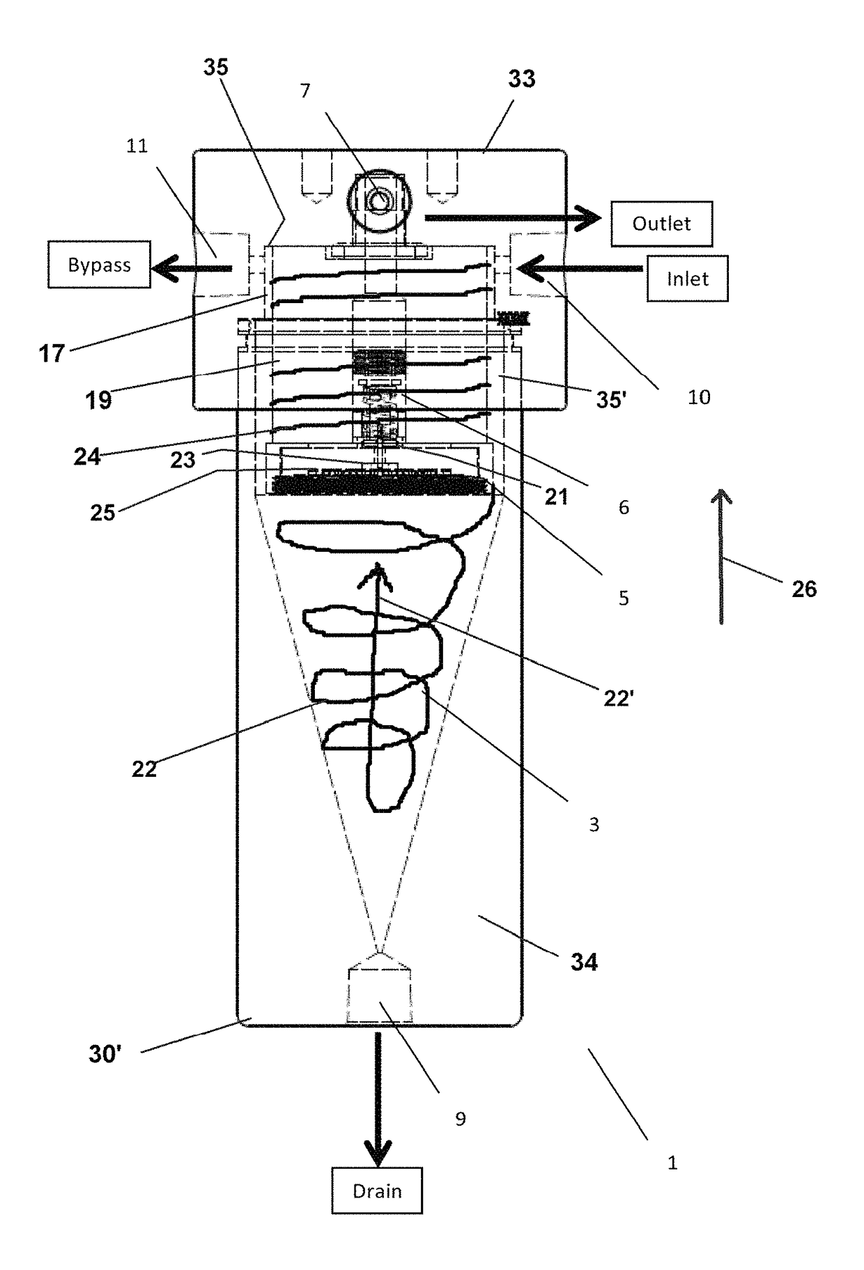
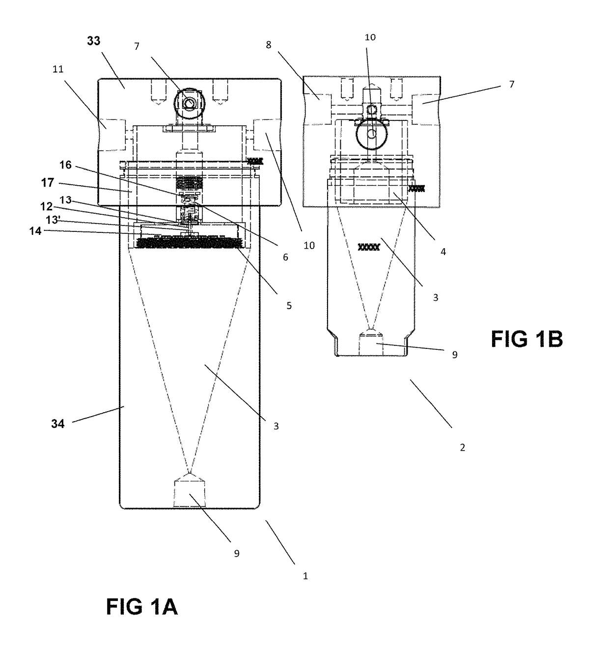
[0057]Further, the described stacking or nesting of the coalescing element 5 within insert 4 in the invention 1 decreases the amount of space required when compared to prior art systems. In the present system, an exemplary coalescing element may comprise, for example, A+ Manufacturing LLC's AVENGER Brand Coalescing membrane filter Model 33(M) and 38(M).

[0058]In addition, in the preferred, first embodiment 1 of the present invention, a liquid block device 6 can be provided downstream and interfacing the coalescing element, shown in the first embodiment 1 situated within insert 4, the liquid block device 6 being configured to activate to prevent passage of liquid therethrough in the event the coalescing element is over-saturated with liquid, resulting in excessive pressure differential, or in the event of pass-through of low surface tension liquids which might be unaffected by the coalescing element.

[0059]In the present, first 1 embodiment illustrated embodiment, a liquid block device...

second embodiment

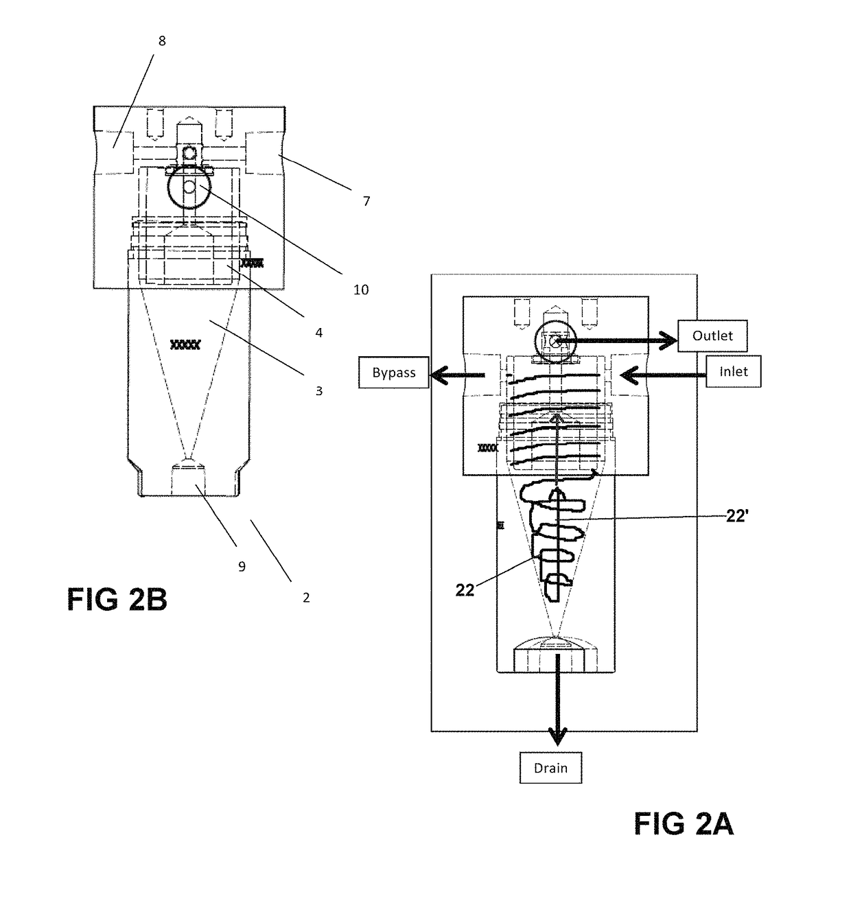
[0068]1 first embodiment of cyclone separator[0069]2 second embodiment[0070]3 separation funnel / cyclone chamber[0071]4 insert[0072]5 coalescing element / membrane filter[0073]6 liquid block[0074]7 outlet port[0075]8 outlet[0076]9 drain port[0077]10 inlet port[0078]11 bypass port[0079]12 biased arm—liquid block[0080]13,′ first, second ends[0081]14 exit side coalescing element[0082]15 passage[0083]16 spring[0084]17 clearance[0085]19 outer surface of insert 4[0086]20 threads[0087]21 seat[0088]22,′ vortex, upward[0089]23 seal[0090]24 fluid flow[0091]25 retention plate[0092]26 build up[0093]27,′ extension, receiver[0094]29 body[0095]30, 30′ first second ends of housing[0096]33 base[0097]34 housing[0098]35,′ cylindrical inner walls[0099]41 connection


PUM

PropertyMeasurementUnit
inner diameteraaaaaaaaaa
pressureaaaaaaaaaa
volumeaaaaaaaaaa

Abstract

A cyclonic filter separator with liquid block capabilities formed to separate liquids in a fluid stream for on-stream and spot sampling of natural gas or the like, particularly pressurized process gas having liquid entrained therein, otherwise referenced as multiphase or “wet”. The present invention incorporates a liquid block apparatus downstream the cyclonic separator to provide to further prevent liquid passing therethrough, ensuring a dry gas sample stream for analysis or the like. A coalescing membrane may be situated intermediate the cyclonic separator and the liquid block, which coalescing membrane may further be linked to the liquid block such that differential pressure associated with the operative state of the membrane causes the liquid block to engage, blocking the flow of fluid therethrough.

Description

BENEFIT CLAIM[0001]The present application claims the benefit of U.S. Provisional patent Application Ser. No. 62 / 087,067 filed Dec. 3, 2014, listing as inventor Valmond Joseph St Amant III, entitled “Cyclonic System for Enhanced Separation of Fluid Samples and the Like”.FIELD OF THE INVENTION[0002]The invention relates to sampling of pressurized process fluids for on-stream and spot sampling of pressurized process fluid such as natural gas or the like having liquid entrained therein, or otherwise referenced as multiphase or “wet”. The present invention contemplates a cyclonic filtration system formed to separate and exclude entrained liquids in the process gas stream, preventing same from entering the sample stream. The preferred embodiment of the invention contemplates the added feature of an coalescing element and liquid block feature to provide a safeguard to exclude any liquid, so as to provide a dry gas sample stream for analysis or the like.BACKGROUND OF THE INVENTION[0003]Nat...

Claims


Application Information

Patent Timeline
Patent Type & Authority Patents(United States)
IPC IPC(8): B01D45/00G01N1/22B01D45/16B01D46/00B01D50/00B01D17/04B01D17/02B01D17/00G01N35/00G01N1/20
CPCG01N1/2211B01D45/16B01D46/0031B01D50/002G01N1/2205G01N1/2247B01D17/0214G01N1/2035Y10T137/0396B01D17/0208B01D17/10G01N2035/00326Y10T137/598B01D17/045G01N1/34G01N33/0011G01N2001/2267G01N33/225B01D46/003B01D46/543B01D50/20
Inventor ST AMANT, III, VALMOND JOSEPH
Owner MAYEAUX HLDG
Why Eureka
Try Eureka