Eureka AIR delivers breakthrough ideas for toughest innovation challenges, trusted by R&D personnel around the world.

Pumpless liquid cooling system

a liquid cooling system and pumpless technology, applied in indirect heat exchangers, laminated elements, light and heating apparatuses, etc., can solve the problems of large volume of liquid cooling systems, inability to meet the needs of traditional air cooling, and occupying more space in electronic systems,

Inactive Publication Date: 2009-02-12
LIU KECHUAN KEVIN
View PDF13 Cites 15 Cited by
  • Summary
  • Abstract
  • Description
  • Claims
  • Application Information

AI Technical Summary

Benefits of technology

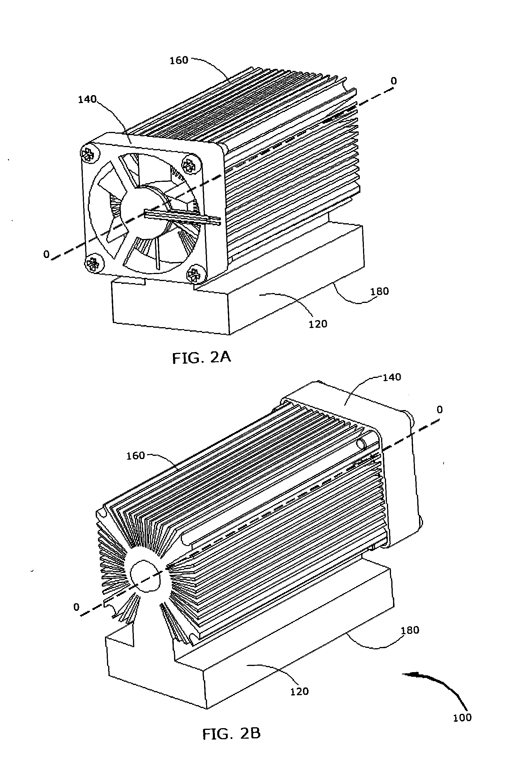
[0010]A pumpless liquid cooling system in accordance with an embodiment of the present invention for removing heat from heat-generating components or systems comprises a heat absorbing portion or cold plate, a heat dissipating portion or heat exchanger and at least one driving device. The heat absorbing portion is configured to have at least one thermal interface surface and a plurality of tubes / channels running inside its body for liquid to pass through. The heat dissipating portion is configured to have a heat dissipating body with an internal cylindrical liquid passage, inlet and outlet communicating to the heat absorbing portion and a plurality of fins extended from or attached thereto its external surface. There is, at least, one impeller running-fitting inside the cylindrical liquid passage and located at one end of the heat dissipating body for the purpose to circulating liquid, and there is an orifice at the other end of the heat dissipating body for the purpose of filling-up liquid and being sealed with a plug thenafter. The impeller is configured to have a shaft with radical spiral vanes and a circular magnet or magnetic disc permanently attached coaxially at one end and having a supporting bearing at the other end. The heat absorbing portion and heat dissipating portion is of unitary construction as a sealed container with working fluid inside. The driving device comprises a frame or stator configured to have the round or rectangular shape with plurality of mounting apertures and a rotor configured to have the cylindrical shape with circular magnet or magnetic disc coaxially attached at the end and a plurality of vanes radically attached or born. The driving device is attached or fastened on the heat dissipating portion and coaxially located with the impeller inside. The impeller driven by the driving device via the magnetic field forces from the pair of magnetic discs circulates liquid between the heat absorbing portion and the heat dissipating portion, and the vanes of driving device, meanwhile, below the air through fins on the heat dissipating portion to reject heat carried by liquid or coolant from the heat absorbing portion. The sealed container and pumpless liquid circulating of this cooling system makes it possible for a liquid cooling system to be simple, cheap, quiet, efficient, reliable, compact and portable.
[0012]It is a further object of the present invention to provide a pumpless liquid cooling system with high heat transfer rate which can be further improved by using high thermal conductive liquid, such as nano-fluid, without changing the physical size of the cooling system and having the possibility for a product to be made smaller without the risk of overheating.

Problems solved by technology

More than ever before, today's electronic products and energy systems are reducing the size and cost, dramatically increasing power and speed, so the traditional air cooling can no longer meets the needs.
Therefore, the liquid cooling system has a big volume and occupies more room in an electronic system and can not achieve the compact and dense packaging, and is not adapted to a small, portable electronic product.
Furthermore, the liquid cooling system has a pump, connecting tubes and fittings with a plurality of connections, which is prone to lead to leakage of the liquid, low reliability of system and a high cost of the product.
Moreover, due to the tubes, fittings, connections the pump and the separation of heat-absorbing member and the heat-dissipating member, the Installation and removal of the liquid cooling system in / from the electronic system is a burdensome and time-consuming work.
It is well known that pump generates noises and vibrations, and has lower reliability, higher cost and maintenance.
This creates the obstacle for building the quiet, portable, reliable and compact electronic and solar products with affordable price.
However, none of them have been able to eliminate the pump in the so-called “Integrated Liquid Cooling System”, which has a big impact on the reliability, cost, size and acoustic noise for a liquid cooling system.

Method used


Image

  • Pumpless liquid cooling system
  • Pumpless liquid cooling system
  • Pumpless liquid cooling system

Examples


Embodiment Construction

[0025]Referring initially to FIGS. 1A and 1B, illustrated are examples of prior art integrated liquid cooling systems 800, 900. The prior art integrated liquid cooling system 800 illustrated in FIG. 1A has a heat absorbing unit 4 containing coolant therein and a heat dissipating unit 2 having a liquid circulating module in communicating with heat absorbing unit 4 via two pipes 100 and 200. The heat generating component 6 is in contact with heat absorbing unit 4. Heat dissipating unit 2 having fan and a plurality of fins (not shown here) to reject heat absorbed by heat absorbing unit 4 and carried by the coolant circulated by a pump (not shown here). Apparently this integrated liquid cooling system has the disadvantages of: 1) having pipes or tubes and fitting for the connections; 2) lack of compact solid construction since the heat absorbing unit and the heat dissipating unit are separated and connected with tubes; 3) having a pump with higher cost and acoustic noise.

[0026]FIG. 1B i...


PUM


Abstract

A pumpless liquid cooling system for removing heat from heat-generating components or systems comprises a heat absorbing portion or cold plate, a heat dissipating portion or heat exchanger and at least one driving device. The heat absorbing portion and the heat dissipating portion are of unitary construction as a sealed container with working fluid inside. The driving device and the heat dissipating portion is co-axially aligned and attached or fastened together. The heat absorbing portion is configured to have at least one thermal contact surface and a plurality of liquid passage within. The heat dissipating portion is configured to have a heat-dissipating body with plurality of external fins and an internal cylindrical liquid passage communicating with those of the heat absorbing portion and having a running fitting impeller driven by the driving device via magnetic forces to circulate the liquid in the heat transfer loop. Meanwhile the driving device moves the cool air through the fins of the heat dissipating portion to reject the heat absorbed by the heat absorbing portion.

Description

CROSS-REFERENCE TO RELATED APPLICATIONS[0001]This patent application is associated to the Provisional patent application filed on Aug. 10, 2007, Application No. 60 / 964,345STATEMENT REGARDING FEDERAL SPONSORED RESEARCH OR DEVELOPMENT[0002]Not ApplicableFIELD OF THE INVENTION[0003]This invention generally relates to the art of liquid cooling system, and in particular, to a pumpless liquid cooling system having the unitary construction of heat-absorbing portion and heat-dissipating portion with a pumpless liquid circulating device for removing heat from heat-generating components or systems.BACKGROUND OF THE INVENTION[0004]Liquid cooling apparatus or liquid cooling systems of a wide variety of designs have been, to some extends, employed to dissipate heat generated by electronic components on printed wiring or circuit boards, video cards, computer CPUs, LED displays and solar energy systems, etc. to prevent the electronic components or systems from failure due to over heating. More tha...

Claims


Application Information

Patent Timeline
IPC IPC(8): F28D15/00
CPCF28F1/16F28F3/12H01L21/4882H01L23/467H01L2924/0002H01L23/473H01L2924/00F28D1/024F28D2015/0291F28F2250/08
Inventor LIU, KECHUAN KEVIN
Owner LIU KECHUAN KEVIN
Why Eureka
Eureka Blog
Learn More