
High Strength Devices and Composites

a high-strength, composite technology, applied in the direction of surface layering apparatus, applications, domestic articles, etc., can solve the problems of not being strong or stiff enough, not being able to meet the requirements of high-load bearing applications, and the plasticiser being injected into high-strength fibres is expected to reduce both the strength and modulus of drawn fibres

Inactive Publication Date: 2008-12-11
SMITH & NEPHEW INC
View PDF102 Cites 18 Cited by
  • Summary
  • Abstract
  • Description
  • Claims
  • Application Information

AI Technical Summary

Benefits of technology

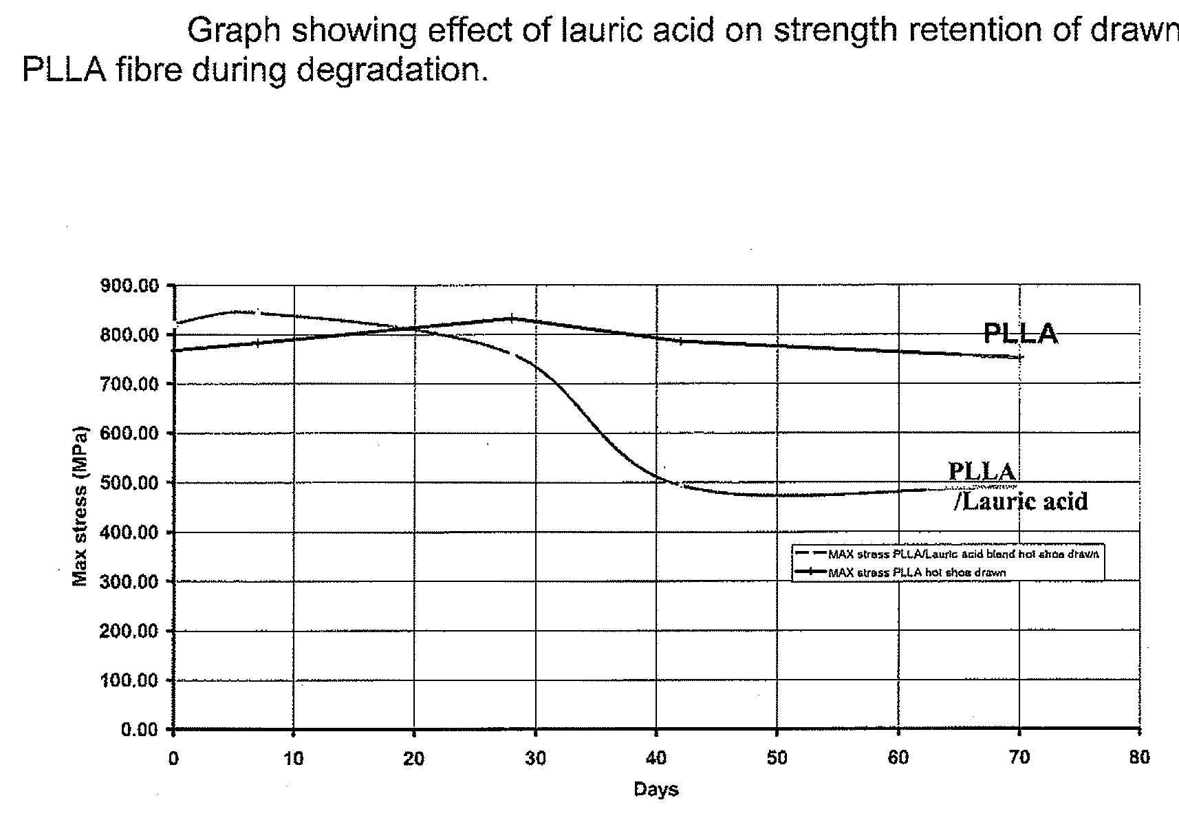
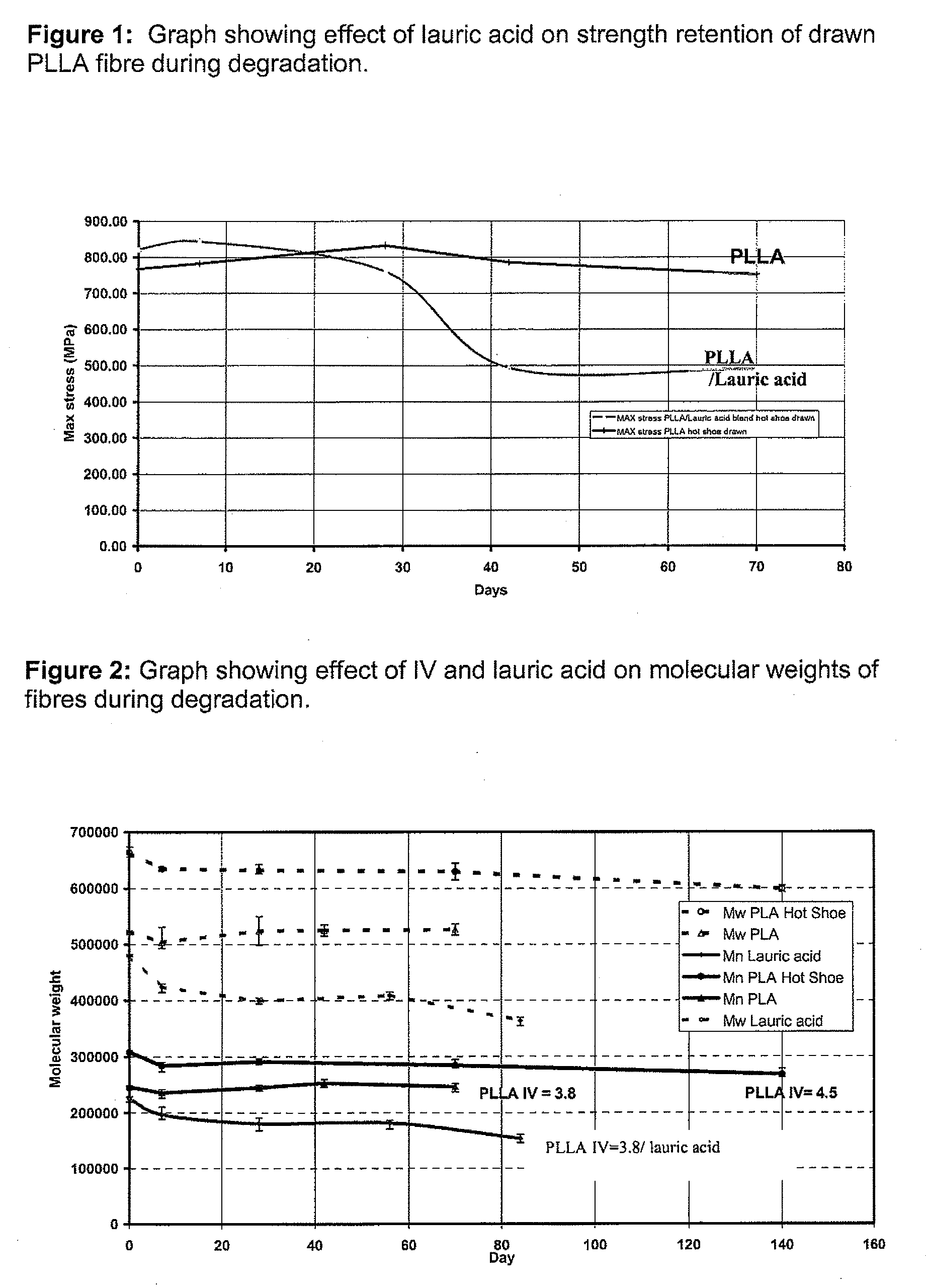
[0015]In a particular advantage the oriented PLA polymer of the invention is characterised by improved degradation properties, equivalent mechanical properties and enhanced draw with respect to the original drawn PLA polymer.
[0018]In an embodiment of the present invention, the additive will not only control the rate of degradation but will delay the onset of the degradation process relative to the acid. This delay may be achieved, aptly by the use of precursors which are convertible to the acidic form of the additive. Suitable precursors are acid anhydrides which will, in an in vivo environment, hydrolyse to the corresponding acid. Example anhydrides include lauric anhydride and benzoic anhydride.

Problems solved by technology

High strength trauma fixation devices (plates, screws, pins etc) are presently made of metal, typically titanium and stainless steel, however metal devices have several well known disadvantages.
However, these materials are not used in high load bearing applications because they are not strong or stiff enough to resist deformation under high load.
Whilst the incorporation of these acid accelerants does not seriously compromise the mechanical properties of moulded P(L)LA block, the incorporation of a plasticiser into high strength fibre is expected to reduce both the strength and modulus of the drawn fibres.
However, the fibres of WO 01 / 46501 and U.S. Pat. No. 5,527,337 are not required to have a high load-bearing performance, but rather are intended to display elastic or absorptive properties and, therefore, would not be suitable for the presently envisaged applications.
We have also found that incorporating these plasticisers increased the degree of draw of the fibres during conventional hot drawing but decreased the drawing temperature.

Method used


Image

  • High Strength Devices and Composites
  • High Strength Devices and Composites

Examples


example 2

Fibre Production

[0058]The following methodology was used to produce both P(L)LA and P(L)LA / LA fibres

Method

[0059]The polymer (P(L)LA-IV=3.8 / Purac) or polymer blend (P(L)LA-IV 3.8 / Purac / lauric acid) was extruded using a Rondol 12 mm extruder. The extruder was fitted with a general-purpose 12 mm screw with a 25:1 L / D ratio. The extruder was fitted with a 2 mm (diameter) die (coated) with a L / D ratio of 6:1. The fibre was produced using a flat temperature profile of 240° C. for all zones. A nominal 0.5 mm diameter fibre was produced (using maximum screw speed of 50 rpm) and hauled off at a rate of 16 meters per minute. The diameter of the fibre was monitored during the run using a Mitutoyo laser micrometer. The extruded fibre was sealed in a foil pouch containing a desiccant sachet and then stored in a freezer at −20° C. prior to further processing.

example 3

Drawn Fibre

[0060]The following methodologies were used to draw both P(L)LA and P(L)LA / LA fibres

Method 1: Hot shoe

[0061]Fibre drawing was carried out using a customised drawing rig. The rig consists of two sets of godets and heated plate (hot shoe). The godets were preset to rotate at different speeds. The fibre was feed from a spindle, through the 1st set of godets, drawn over the hot shoe and around the 2nd set of godets. The drawn fibre was finally collected on a Leesona fibre winder.

Results

[0062]The fibres were drawn under various temperatures and speeds to produced fibres with different properties as shown in Table 1.

TABLE 1Temp 1stSpeed ofSpeed ofTemp 2ndSpeed ofSpeed ofFibreMaxpassGodet 1Godet 2passGodet 1Godet 2DiaTotalstressModulus(C.)(RPM)(RPM)(C.)(RPM)(RPM)(mm)draw(MPa)(GPa)(a) PLLA / LA160337———0.138209.0529.89.5150342———0.127248.0689.610.916041618010270.099405.0823.08.4(b) PLLA160324———0.13621673811.6180334———0.145190.271410.5716041618010180.178126.2759.08.7

[0063]These dra...

example 4

Lauric Acid Determination

Method

[0067]Approx. 0.1 g of each PLA / LA sample was dissolved in approx. 10 ml chloroform. Internal standard was added via glass pipette (0.9 mg / ml Hexanoic acid in acetone). Samples were left overnight to dissolve. 20-30 ml of diethyl ether was added to precipitate the polymer. An aliquot of each solution was filtered through 0.45 μm PTFE GDX Whatman syringe filters into injection vials. The analysis was carried out using Gas Chromatography under the following conditions:—

GC System:3Column:Phenomenex ZB-FFAP (30 m × 0.53 mm × 1 μm)Head pressure:6psiCarrier gas:HeliumSplit gas flow:15ml / minHydrogen gas flow:45ml / minNitrogen gas flow:20ml / minOven Program:Initial temp:200° C.Initial time:2minRate of ramp:5°C. / minFinal temp:240°C.Total Run Time:10minInjector temp:250°C.Injection volume:1μlDetector temp:250°C.Detection:FID

Results

[0068]Table 3 shows the amount of lauric acid contained in each P(L)LA / LA fibre.

TABLE 3AmountMeanSample Details(% w / w)(% w / w)PLA (3.8 I...


PUM

PropertyMeasurementUnit
Mnaaaaaaaaaa
Mnaaaaaaaaaa
tensile strengthaaaaaaaaaa

Abstract

An oriented implantable, biodegradable device is disclosed. The oriented implantable, biodegradable device is formed from a homogeneous polymer blend comprising a polylactic acid in admixture, in an amount of not more than 10% by weight of the polymer blend, with an additive which both plasticises polymer draw and is a degradation accelerant. The polymer comprised within the blend may be a uniaxial, biaxial or triaxial orientation. Also disclosed is a composite thereof, processes for the preparation thereof, and The implantable biodegradable device may be used as a high strength trauma fixation device suitable for implantation into the human or animal body. As examples, the high strength trauma fixation device may take the form of plates, screws, pins, rods, anchors or scaffolds.

Description

[0001]This application claims the benefit of U.K. Provisional Application No. 0516943.8 filed Aug. 18, 2005 and U.K. Provisional Application No. 0523318.4, filed Nov. 16, 2005 both entitled “High strength fibres and composites” and the entire contents of which are hereby incorporated by reference.TECHNICAL FIELD OF THE INVENTION[0002]This invention relates to biodegradable polymeric devices and composites, particularly to bioresorbable devices and composites and to artifacts made therefrom and their uses.BACKGROUND OF THE INVENTION[0003]High strength trauma fixation devices (plates, screws, pins etc) are presently made of metal, typically titanium and stainless steel, however metal devices have several well known disadvantages.[0004]Currently amorphous or semi-crystalline bioresorbable polymers such as poly (glycolic acid) (PGA) and poly (lactic acid) (PLA) are typically used to produce low load bearing devices—such as suture anchors, screws or tacs. One of the main criteria for usi...

Claims


Application Information

Patent Timeline
Patent Type & Authority Applications(United States)
IPC IPC(8): A61L27/14A61F2/00A61L17/12
CPCA61L27/18A61L27/48A61L27/50A61L27/502C08L67/04
Inventor BROWN, MALCOLM NMIHALL, MICHAEL ANDREWROSE, JOHN NMIBULL, ALAN NMIFARRAR, DAVID F.
Owner SMITH & NEPHEW INC
Learn More