
Photovoltaic Devices and Photovoltaic Roofing Elements Including Granules, and Roofs Using Them

a technology of photovoltaic roofs and photovoltaic elements, applied in the direction of pv power plants, sustainable buildings, transportation and packaging, etc., can solve the problems of increasing the cost of fossil fuels, increasing the cost of fossil fuel combustion, and not being aesthetically pleasing, so as to achieve significant photovoltaic power

Inactive Publication Date: 2008-11-06
CERTAINTEED CORP
View PDF37 Cites 81 Cited by
  • Summary
  • Abstract
  • Description
  • Claims
  • Application Information

AI Technical Summary

Benefits of technology

[0014]The photovoltaic devices, photovoltaic roofing elements, roofs and methods of the present invention result in a number of advantages over prior art methods. For example, the photovoltaic devices and photovoltaic roofing elements of the present invention can be configured to match, harmonize and / or complement a desired type of roofing material. The roofs of the present invention can be aesthetically pleasing yet still generate significant photovoltaic power.

Problems solved by technology

First, fossil fuels have become more and more expensive due to increasing scarcity and unrest in areas rich in petroleum deposits.
Second, there exists overwhelming concern about the effects of the combustion of fossil fuels on the environment, due to factors such as air pollution (from NOx, hydrocarbons and ozone) and global warming (from CO2).
Often perched on an existing roof in panel form, these photovoltaic elements are quite visible and generally not aesthetically pleasant.
However, these colors frequently do not work well aesthetically with the rest of the roof.
Nonetheless, to date, installations have appeared to have been motivated by purely practical and functional considerations; there appears to have been no coordination between the appearance of the photovoltaic cells and the roofing materials (e.g., tiles or shingles) upon which they are mounted.
Lack of aesthetic appeal is especially problematic in residential buildings with non-horizontally pitched roofs; people tend to put a much higher premium on the appearance of their homes than they do on the appearance of their commercial buildings.
While there have been attempts integrate photovoltaic elements into more conventional roofing materials, none appear to have addressed the fact that the photovoltaic element itself presents a generally aesthetically undesirable surface.

Method used


Image

  • Photovoltaic Devices and Photovoltaic Roofing Elements Including Granules, and Roofs Using Them
  • Photovoltaic Devices and Photovoltaic Roofing Elements Including Granules, and Roofs Using Them
  • Photovoltaic Devices and Photovoltaic Roofing Elements Including Granules, and Roofs Using Them

Examples


Embodiment Construction

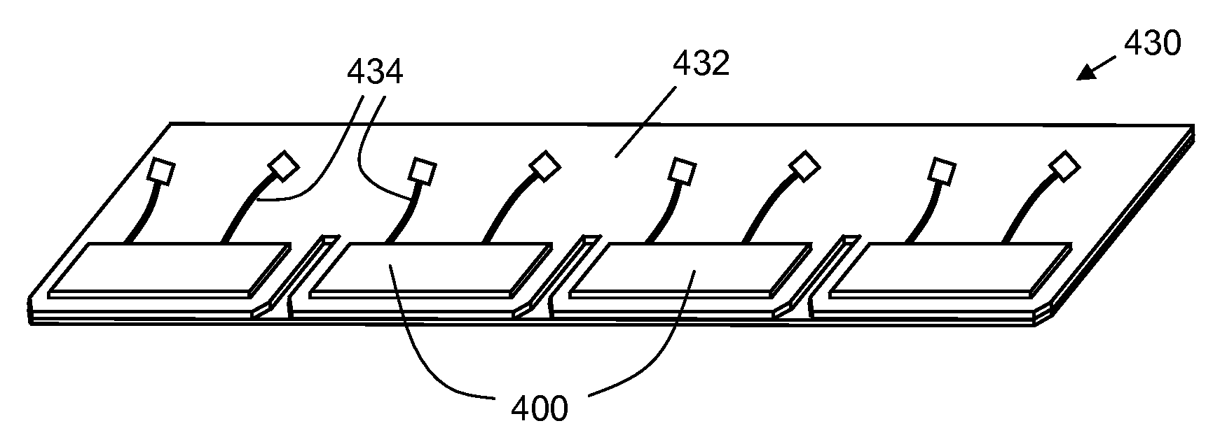
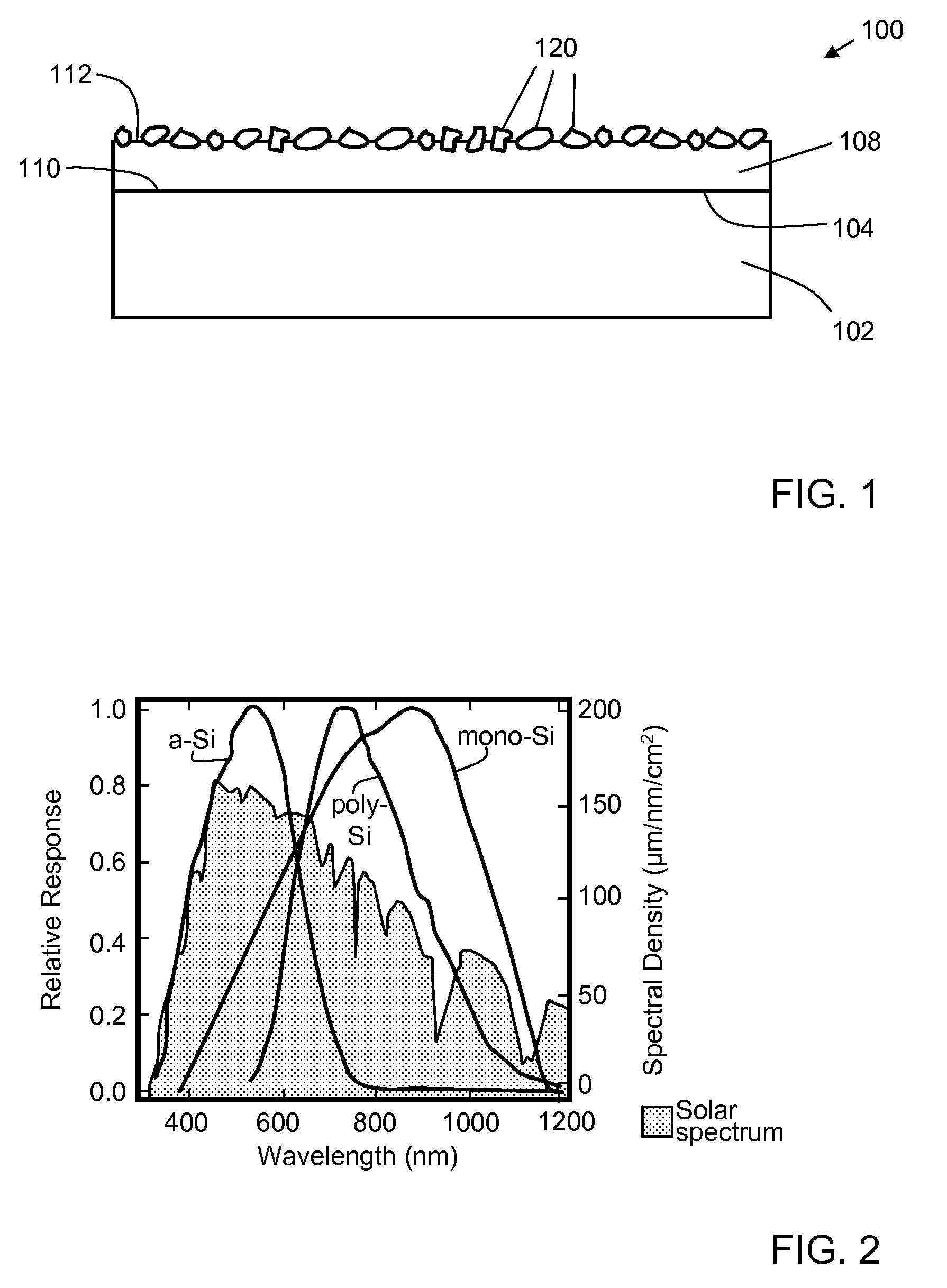
[0030]One aspect of the invention is a photovoltaic device. One example of a photovoltaic device according to this aspect of the invention is shown in schematic cross-sectional view in FIG. 1. Photovoltaic device 100 includes a photovoltaic element 102, which has an active face 104 and an operating wavelength range. Photovoltaic element 102 includes one or more photovoltaic cells individually electrically connected so as to operate as a single unit.

[0031]Photovoltaic element 102 may be based on any desirable photovoltaic material system, such as monocrystalline silicon; polycrystalline silicon; amorphous silicon; III-V materials such as indium gallium nitride; II-VI materials such as cadmium telluride; and more complex chalcogenides (group VI) and pnicogenides (group V) such as copper indium diselenide. For example, one type of suitable photovoltaic element includes an n-type silicon layer (doped with an electron donor such as phosphorus) oriented toward incident solar radiation on ...


PUM

PropertyMeasurementUnit
Fractionaaaaaaaaaa
Fractionaaaaaaaaaa
Fractionaaaaaaaaaa

Abstract

The present invention includes photovoltaic devices and photovoltaic roofing elements comprising a photovoltaic element having an active face and an operating wavelength range; a polymer structure having (a) a bottom surface disposed on the active face of the photovoltaic element and (b) a top surface; and a plurality of granules disposed on the top surface of the polymer structure. Roofs including the photovoltaic devices and photovoltaic roofing elements of the present invention may be configured to have an aesthetically desirable appearance while retaining high photovoltaic efficiency.

Description

BACKGROUND OF THE INVENTION[0001]1. Field of the Invention[0002]The present invention relates generally to photovoltaic devices. The present invention relates more particularly to photovoltaic devices with aesthetic properties making them suitable for use in roofing applications.[0003]2. Technical Background[0004]The search for alternative sources of energy has been motivated by at least two factors. First, fossil fuels have become more and more expensive due to increasing scarcity and unrest in areas rich in petroleum deposits. Second, there exists overwhelming concern about the effects of the combustion of fossil fuels on the environment, due to factors such as air pollution (from NOx, hydrocarbons and ozone) and global warming (from CO2). In recent years, research and development attention has focused on harvesting energy from natural environmental sources such as wind, flowing water and the sun. Of the three, the sun appears to be the most widely useful energy source across the ...

Claims


Application Information

Patent Timeline
IPC IPC(8): H01L31/02H01L31/042
CPCE04D1/20E04D1/26E04D5/12E04D7/005E04D2001/005H01L31/02168Y10T156/10Y02B10/12Y02E10/50H02S20/23H02S20/25Y10T428/24372H01L31/0236H01L31/02366Y02B10/10
Inventor JACOBS, GREGORY F.SHAW, WAYNE E.
Owner CERTAINTEED CORP
Learn More